Control method and system for reducing the common-mode current in power converter

A power converter, common mode current technology, applied in the field of control and system for reducing the common mode current in the power converter, can solve the unsatisfactory, reduce the common mode voltage of the variable speed drive, can not etc.

Active Publication Date: 2012-05-09
SCHNEIDER TOSHIBA INVERTER EUROPE SAS
View PDF3 Cites 8 Cited by
  • Summary
  • Abstract
  • Description
  • Claims
  • Application Information

AI Technical Summary

Problems solved by technology

For the previously cited literature, this approach is unsatisfactory because it does not allow sufficient reduction of the common-mode voltage in the variable speed drive

Method used


Image

  • Control method and system for reducing the common-mode current in power converter
  • Control method and system for reducing the common-mode current in power converter
  • Control method and system for reducing the common-mode current in power converter

Examples


Embodiment Construction

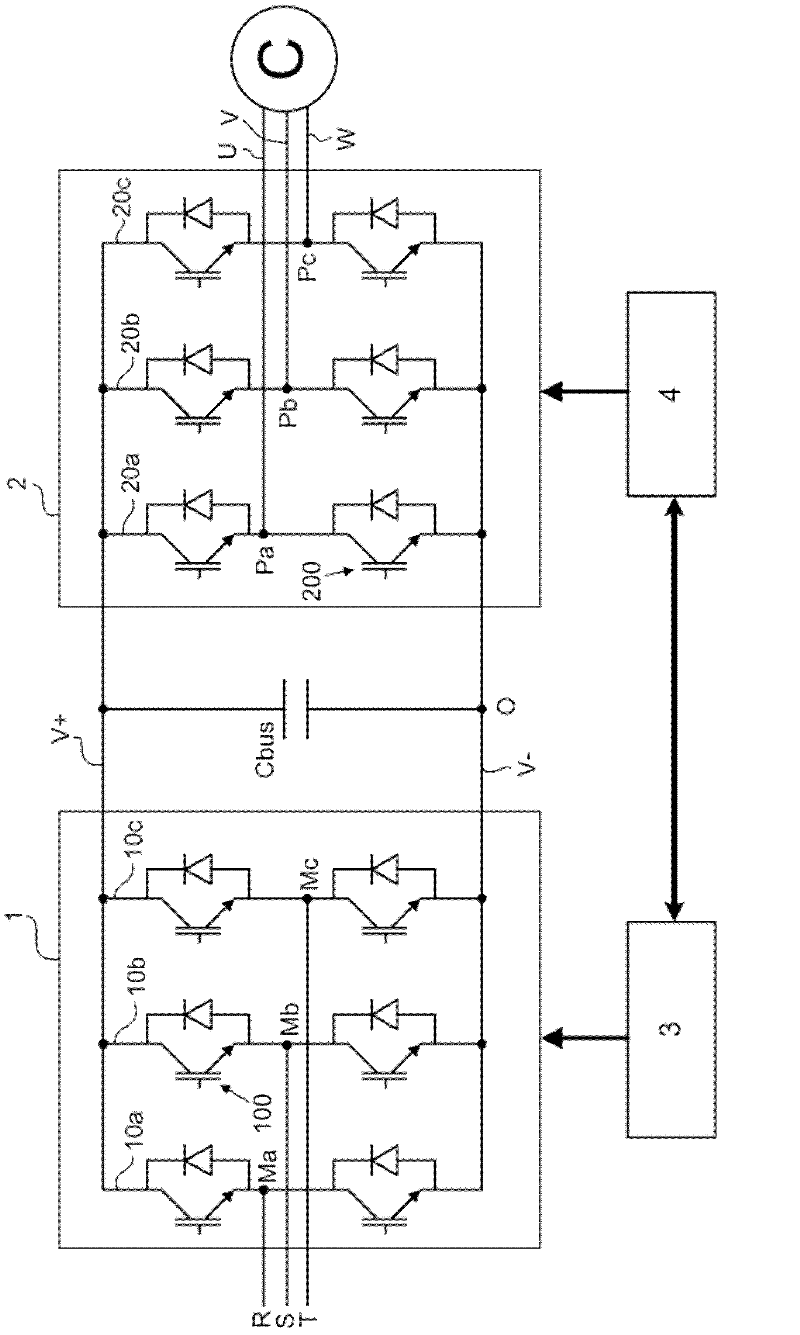
[0034] refer to figure 1 and 2 As is known, a power converter, for example of the variable speed drive type, comprises a rectifier stage 1, 1', a DC supply bus and an inverter stage 2, 2'. Different power converter configurations are possible. The invention finds most particular application in power converters comprising active rectifier stages.

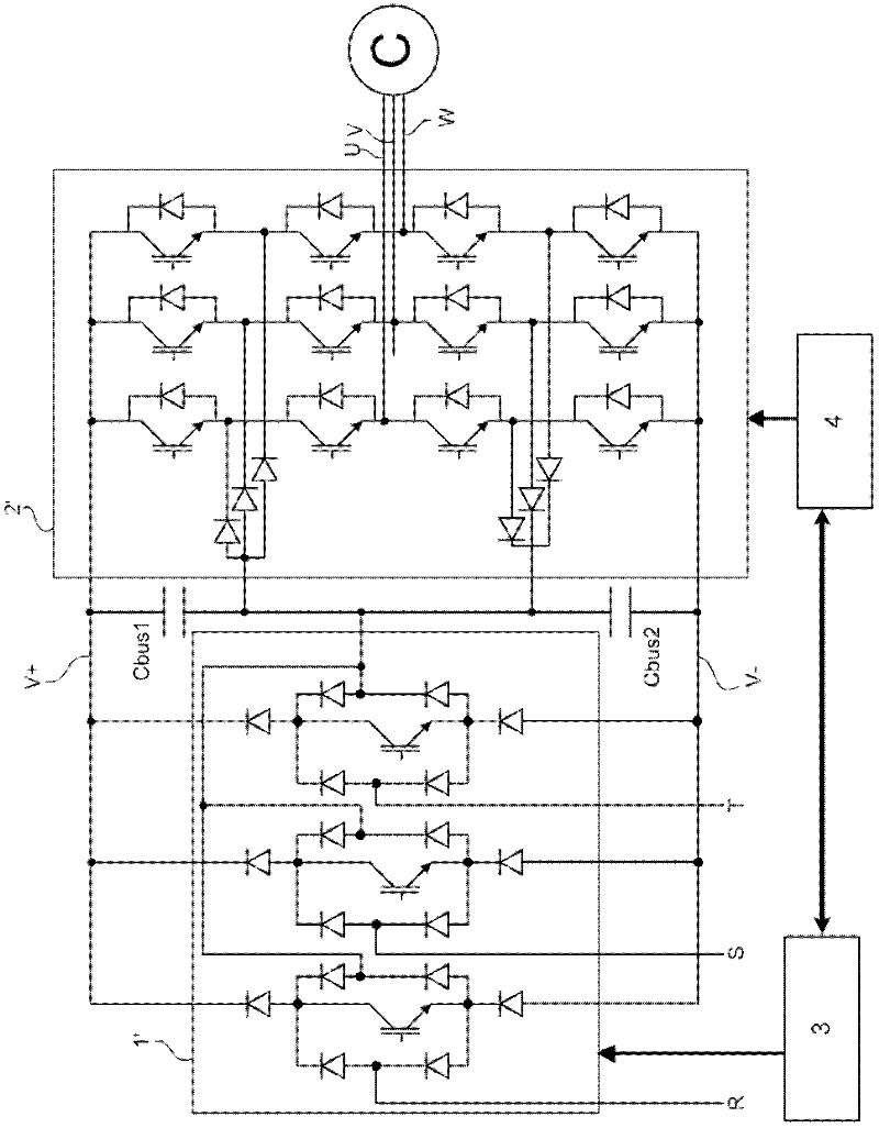
[0035] figure 1 represents, for example, a two-level variable speed drive with active rectifier stage 1 . figure 2 A three-level variable speed drive is shown, for example employing an inverter stage 2' of NPC (Neutral Point Clamped) type and an active rectifier stage 1' of Vickers bridge type. Other configurations are also possible, such as using an inverter stage with flyback capacitors.

[0036] refer to figure 1 , the rectifier stage 1 is connected to the mains supply via AC inductors (not shown), eg on the three input phases R, S, T for the three-phase rectifier stage 1 . Typically, in variable speed drives, the rectifie...


PUM


Abstract

The invention relates to a control method and system intended to reduce the common-mode current in a power converter which comprises a rectifier stage (1, 1') connected to a number of input phases (R, S, T) and an inverter stage (2, 2') connected to a number of output phases (U, V, W). On each switching period, the rectifier stage (1, 1') and the inverter stage (2, 2') are controlled in a synchronized manner so that a variation of potential applied to an input phase (R, S, T) always corresponds to a variation of potential of the same sign applied to an output phase (U, V, W).

Description

technical field [0001] The present invention relates to control methods and systems for reducing voltage and common mode current in power converters. Background technique [0002] The power converter comprises a plurality of input phases connected to the mains supply, for example three input phases if connected to a three-phase mains supply. Connected to its input phases, a conventional converter includes a rectifier stage for converting the AC voltage provided by the mains supply into a DC voltage. The converter also includes a power supply bus to which a DC voltage is applied, a first power supply line having a positive potential and a second power supply line having a negative potential, and a bus capacitor connected between the first power supply line and the second power supply line and configured to The DC voltage on the bus is kept constant. Downstream of the bus capacitors, variable speed drive type power converters also include an inverter stage with a number of s...

Claims


Application Information

Patent Timeline
Patent Type & Authority Applications(China)
IPC IPC(8): H02M5/458
CPCH02M1/44H02M2001/123H02M5/4585H02M1/123
Inventor A.维德特P.罗伊泽莱特M.西亚姆
Owner SCHNEIDER TOSHIBA INVERTER EUROPE SAS
Why Eureka
Try Eureka