

Stress treatment device and turbine manufacture method
A stress treatment and turbine technology, applied in the direction of turbines, manufacturing tools, blade support components, etc., can solve problems such as increased centrifugal force of blades, achieve the effect of improving fatigue strength and reducing stress corrosion cracking
- Summary
- Abstract
- Description
- Claims
- Application Information
AI Technical Summary
Problems solved by technology
Method used
Image

Examples
Embodiment approach 1
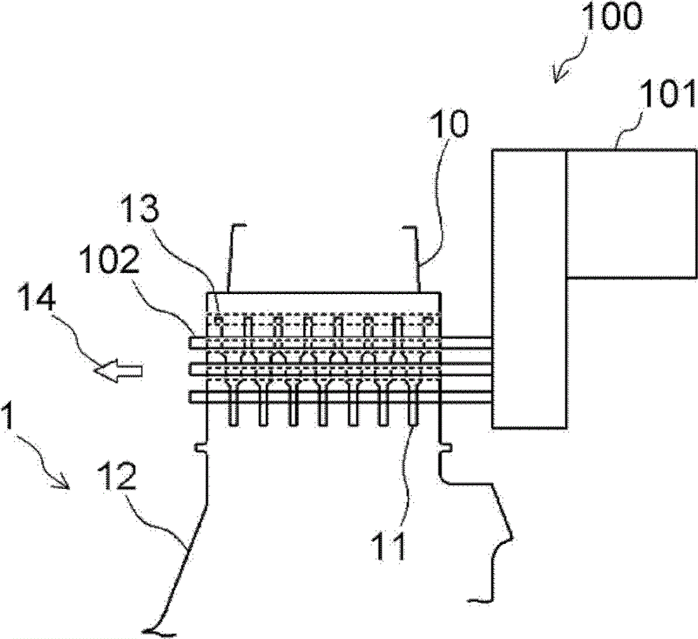
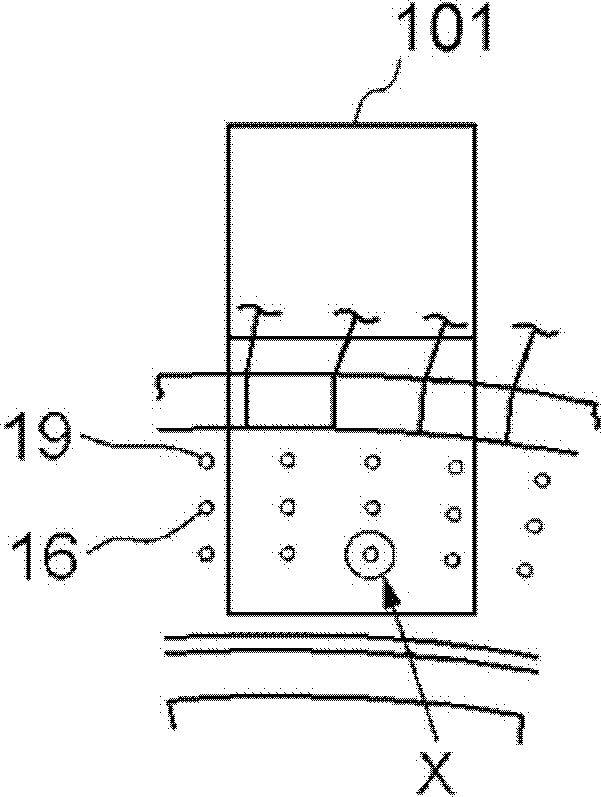
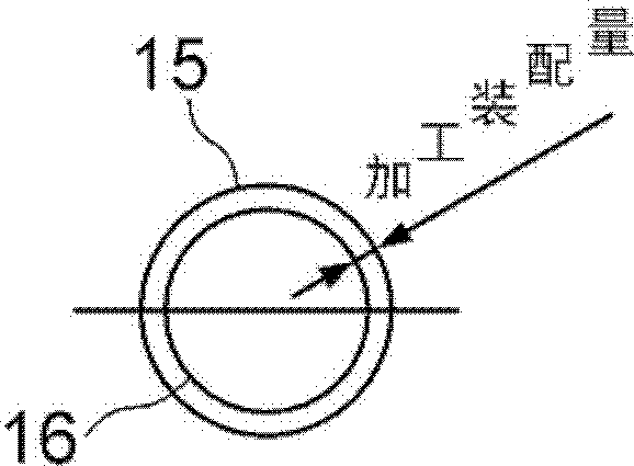
[0074] Embodiments will be described below with reference to the drawings. Figure 1A ~ Figure 1C This is a diagram for explaining the simultaneous reaming of the turbine rotor blade 10 and the disk 12 . Figure 1A is a front view showing the combined structure of the turbine rotor blade 10 and the disk 12, Figure 1B is the side view, Figure 1C yes Figure 1B Enlarged view of part X. figure 2 It is a diagram for explaining the configuration of the stress treatment device 24 according to Embodiment 1, and is a front view showing stress improvement performed on the pin hole 15 of the joint structure of the turbine rotor blade 10 and the disk 12 . image 3 It means viewing from direction A figure 2 composition to the view. Figure 4 yes means figure 2 Enlarged view of the head shown. However, in the following figures, the same reference numerals are assigned to the same components.
[0075] The turbine rotor blade 10 has a blade fork 11 at the lower end. The disc 12 ...
Embodiment approach 2
[0120] Figure 9 It is a figure for explaining the structure of the stress processing apparatus 24 which concerns on Embodiment 2, and is a front view which shows the time of stress improvement to the pin hole 15 of the disk 12. FIG. Since the structure of the stress treatment device 24 in Embodiment 2 is the same as figure 2 The shown stress treatment device has the same configuration, so detailed description is omitted.
[0121] In this stress treatment device 24 , a guide plate 59 having the same shape as that of the blade fork 11 is arranged at a position where the turbine rotor blade 10 is removed. After the disk yoke 13 and the guide plate 59 are temporarily pre-positioned by the pin, shot blasting is performed on the inner surface of the pin hole 15 to form the compressive stress region C. Here, since the positioning of the position of the pin hole 15 and the position of the construction head 38 is the same as that of the stress treatment device in Embodiment 1, desc...
Embodiment approach 3
[0125] Next, a case where shot peening is performed on the turbine rotor blade 10 removed from the rotor 1 will be described. Figure 10A ~ Figure 10C It is a figure which shows the turbine rotor blade 10 at the time of single-piece construction. Figure 10A , Figure 10B is a perspective view of a turbine blade, Figure 10C is the partial side view from the x direction. Figure 11 It is a perspective view showing the turbine rotor blade 10 when two sheets are stacked and constructed. Figure 12It is a diagram for explaining the configuration of the stress treatment device 60 according to Embodiment 3, and is a perspective view showing the stress treatment device 60 for improving the stress on the inner surface of the pin hole 15 of the removed turbine rotor blade 10 .
[0126] The turbine rotor blade 10 has semicircular holes 15a, 15b located in the width direction. Three of these 15a and 15b are formed along the radial direction of the rotor 1, and constitute a radical s...
PUM
 Abstract
Description
Claims
Application Information