


Quick Research
Generate reliable direction feasibility study reports for your R&D in just a few steps.

Technical Q&A
Discover and master advanced knowledge NOW. Basics, ideas, possibilities, all at once.

Find Solutions
As an expert in R&D theories, this can generate solutions to your technical problems instantly.

Evaluate Feasibility
Analyze your overall solution with one click, know your potential R&D risks in advance.

Monitor Landscape
Get weekly tech updates, stay abreast of the latest tech innovations and key insights.
Projection optical system and image projector
A technology of projection optical system and optical system, which is applied in the direction of optics, image communication, TV system components, etc., can solve the problems of increasing dust deposition and unusability
- Summary
- Abstract
- Description
- Claims
- Application Information
AI Technical Summary
Problems solved by technology
Method used
Image

Examples
no. 1 example
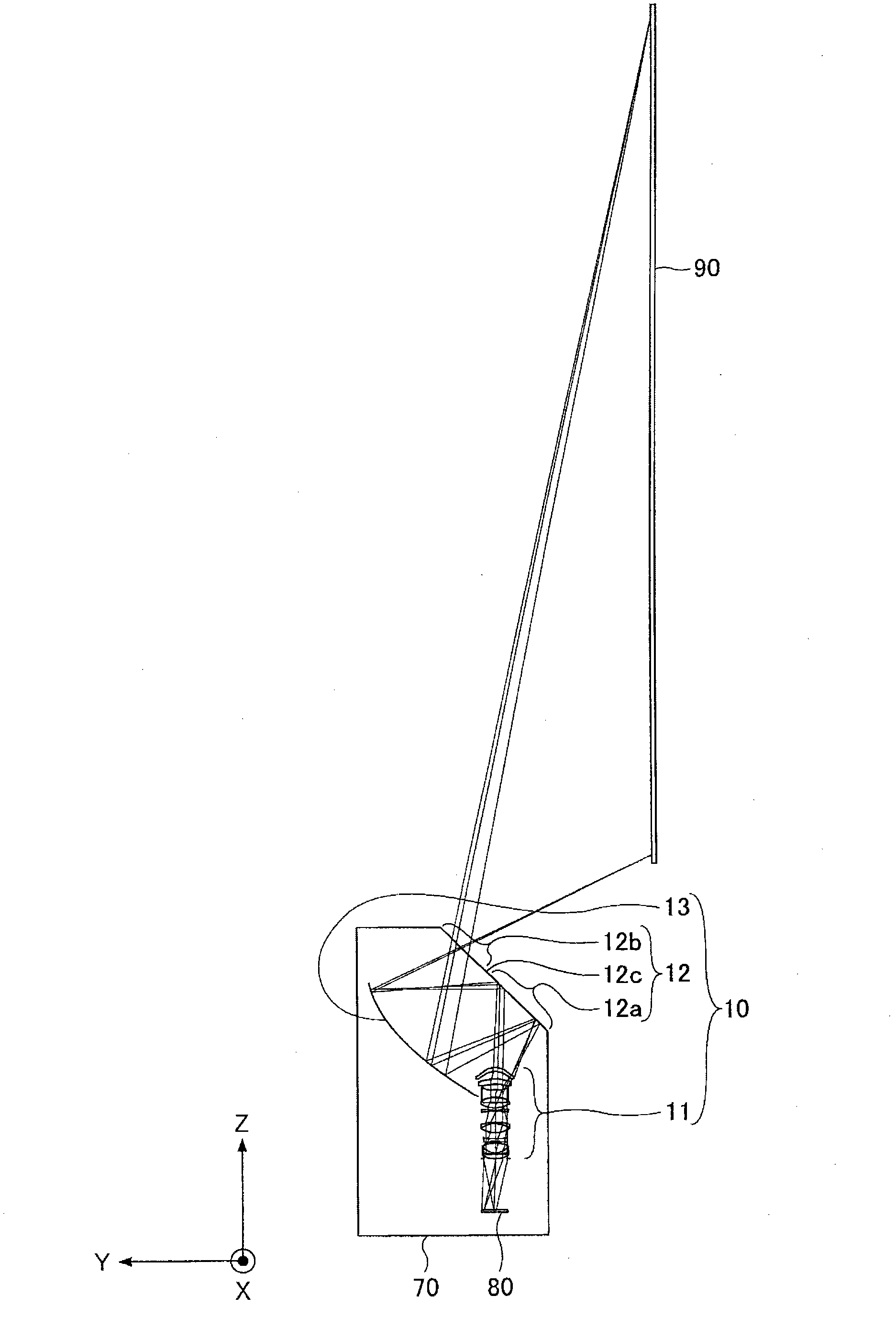
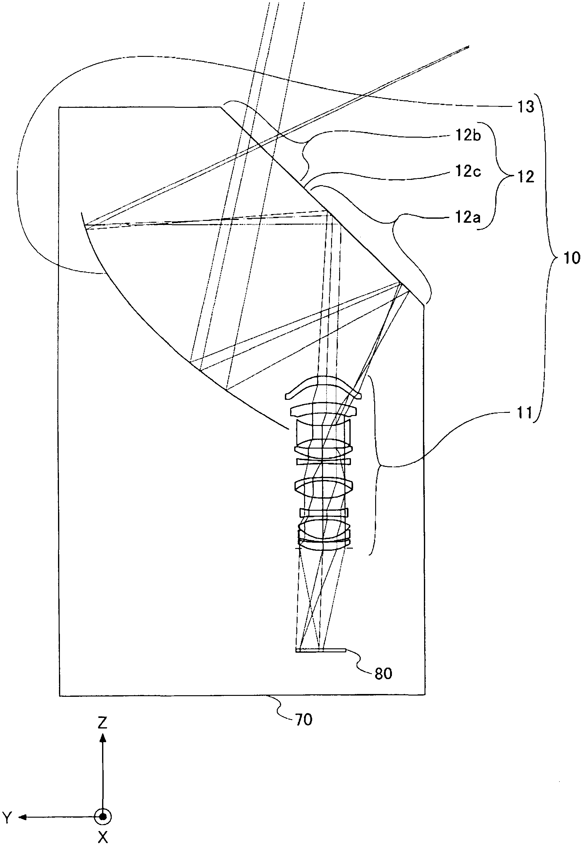
[0036] figure 1 is to show a ray diagram of the projection optical system according to the first embodiment. figure 2 for figure 1 A partial enlargement of the . exist figure 1 and figure 2 In the coordinate system of , X, Y and Z indicate the major axis direction, the normal direction and the minor axis direction of the screen 90 (projection surface), respectively.
[0037] refer to figure 1 and figure 2 , the projection optical system 10 includes a first optical system 11 , a second optical system 12 and a third optical system 13 .
[0038] In the projection optical system 10, the first optical system 11 is a coaxial optical system including at least one refractive system (lens), and has positive diopter as a whole. In this embodiment, the first optical system 11 is composed of 11 lenses, but is not limited to this structure.
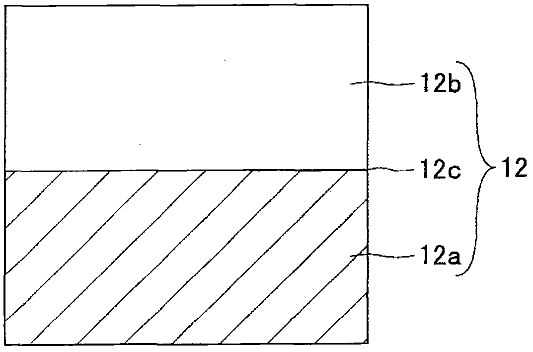
[0039] refer to figure 1 and figure 2 , the second optical system 12 includes a reflective area 12a and a transmissive area 12b, the re...
no. 2 example
[0073] In the first embodiment, the case where the second optical system 12 is planar (flat) is shown. In the second embodiment, a case where the second optical system is bent is shown.
[0074] Figure 9 is to show a ray diagram of the projection optical system according to the second embodiment. Figure 10 for Figure 9 A partial enlargement of the . exist Figure 9 and Figure 10 In the coordinate system of , X, Y and Z indicate the major axis direction, the vertical direction and the minor axis direction of the screen 90, respectively.
[0075] refer to Figure 9 and Figure 10 , projection optical system 20 and projection optical system 10 ( figure 1 and figure 2 ) is that the second optical system 12 is replaced by the second optical system 22.
[0076] The second optical system 22 includes a reflective area 22a and a transmissive area 22b. The second optical system 22 is fixed close to the opening of the housing 70 . The second optical system 22 is bent at ...
no. 3 example
[0088] In the first embodiment, an example in which the second optical system 12 is flat is shown, and in the second embodiment, an example in which the second optical system 22 is curved is shown. In the third embodiment, an example in which the transmissive area is inclined toward the screen in the second embodiment is shown.
[0089] Figure 15 is to show a ray diagram of the projection optical system according to the third embodiment. Figure 16 to show Figure 15 A partial enlarged view of . exist Figure 15 and Figure 16 In the coordinate system of , X, Y and Z indicate the major axis direction, the vertical direction and the minor axis direction of the screen 90, respectively.
[0090] refer to Figure 15 and Figure 16 , projection optical system 30 and projection optical system 20 ( Figure 6 and Figure 10 ) is that the second optical system 32 is used instead of the second optical system 22.
[0091] The second optical system 32 includes a reflective area...
PUM
 Abstract
Description
Claims
Application Information
 - R&D Engineer
- R&D Manager
- IP Professional
- Industry Leading Data Capabilities
- Powerful AI technology
- Patent DNA Extraction
Browse by: Latest US Patents, China's latest patents, Technical Efficacy Thesaurus, Application Domain, Technology Topic, Popular Technical Reports.
© 2024 PatSnap. All rights reserved.Legal|Privacy policy|Modern Slavery Act Transparency Statement|Sitemap|About US| Contact US: help@patsnap.com