Cooling module for optical projection system

A projection optical system and heat dissipation module technology, applied in optics, cooling/ventilation/heating transformation, instruments, etc., can solve problems such as abnormal projection color, system shutdown, access, etc., to reduce noise and avoid system abnormalities

Inactive Publication Date: 2012-05-16
CORETRONIC
View PDF8 Cites 16 Cited by
  • Summary
  • Abstract
  • Description
  • Claims
  • Application Information

AI Technical Summary

Problems solved by technology

However, the above-mentioned design is also easy to cause dust to enter the projector 100b along with the cooling air flow, causing the light sensor 106 or the position indicator 104 to produce abnormal projected colors due to the adhesion of dust, and even cause the system to shut down abnormally.
In addition, the color wheel 102, the light sensor 106, and the light integrating column 108 are simultaneously cooled only by the airflow from the air outlet of the fan 202, which cannot provide good heat dissipation efficiency.
Furthermore, Taiwan Patent No. TWI322921 and Taiwan Patent No. TWI235281 both disclose heat dissipation designs with fans and air guide structures, but the airflow concentration effect of these designs is not good, so the cooling effect is limited

Method used


Image

  • Cooling module for optical projection system
  • Cooling module for optical projection system
  • Cooling module for optical projection system

Examples


Embodiment Construction

[0043] The aforementioned and other technical contents, features and effects of the present invention will be clearly presented in the following detailed description of the embodiments with reference to the drawings. The directional terms mentioned in the following embodiments, such as: up, down, left, right, front or back, etc., are only directions referring to the attached drawings. Accordingly, the directional terms are used to illustrate and not to limit the invention.

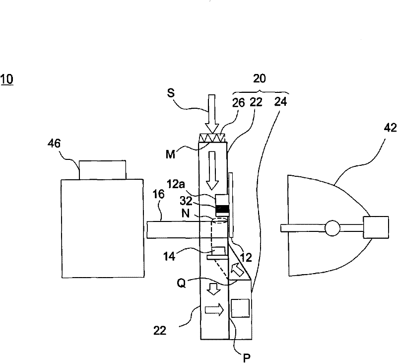
[0044] figure 2 is a partial cross-sectional schematic diagram of a projector according to an embodiment of the present invention, and image 3 It is a partial schematic diagram of a projection optical system according to an embodiment of the present invention. Please also refer to figure 2 and image 3 The projection optical system 10 of this embodiment at least includes a color wheel 12 , a photosensor 14 , an integration rod 16 and a heat dissipation module 20 . In this embodiment, when projectio...


PUM


Abstract

The invention provides a cooling module for an optical projection system. The cooling module comprises a flow channel, a fan and an air filtering device. The flow channel is arranged in the optical projection system and is provided with a suction port and an exhaust port. The fan is arranged in the flow channel and is provided with an air inlet and an air outlet. The fan is used for bringing air flow in the flow channel; after the air flow enters into the flow channel from the suction port, the air flow sequentially passes through the air inlet and the air outlet and goes out of the flow channel from the exhaust port. A color wheel and a photo-detector are arranged in the flow channel and are arranged between the suction port of the flow channel and the air inlet of the fan. An optical integral column is arranged in the flow channel and is located between the air outlet of the fan and the exhaust port of the flow channel. The air filtering device is arranged on the suction port of the flow channel. The cooling module provided by the invention can provide good cooling and filtering effects.

Description

【Technical field】 [0001] The present invention relates to a heat dissipation module, and in particular to a heat dissipation module for a projection optical system. 【Background technique】 [0002] Figure 1A It is a partial schematic diagram of a conventional projector. Such as Figure 1A As shown, the working principle of the projector 100a is that the light emitted by a light source (not shown) passes through a high-speed rotating color wheel (colorwheel) 102, and then irradiates a digital micromirror device (not shown) to form a projection. image. In order to make the switch state of the microlens on the digital micromirror device cooperate with the rotation of the color wheel 102, a position indicator (index mark) 104 is generally attached to the color wheel motor 102a of the color wheel 102, and a light sensor A photo sensor 106 senses the area of ​​the color wheel through which the current light passes, so as to project an image of a desired color. As far as the abo...

Claims


Application Information

Patent Timeline
Patent Type & Authority Applications(China)
IPC IPC(8): G03B21/16G03B21/14H05K7/20
CPCG03B21/16
Inventor 戴嘉鸿林宗庆
Owner CORETRONIC
Why Eureka
Try Eureka