

Powder coating for photovoltaic module
A photovoltaic module and backplane technology, applied in photovoltaic power generation, coating, friction discharge injection, etc., can solve the problems of reduced yield and long time-consuming preparation process
- Summary
- Abstract
- Description
- Claims
- Application Information
AI Technical Summary
Problems solved by technology
Method used
Image

Examples
Embodiment Construction
[0019] Embodiments of the invention are discussed in more detail below. However, this embodiment may be an application of various inventive concepts, and may be embodied in various specific ranges. The specific embodiments are for illustrative purposes only and do not limit the scope of the disclosure.
[0020] A reference to the singular may include the plural (eg "a" may mean one, at least one or more) unless the context specifically mentions otherwise. As used herein, "about" is used to modify any quantity that may vary slightly, but which does not alter the essence. If there is no special explanation in the text, it means that the error range of the value modified by "about" is generally allowed to be within the range of the upper and lower limits defined in the present embodiment.
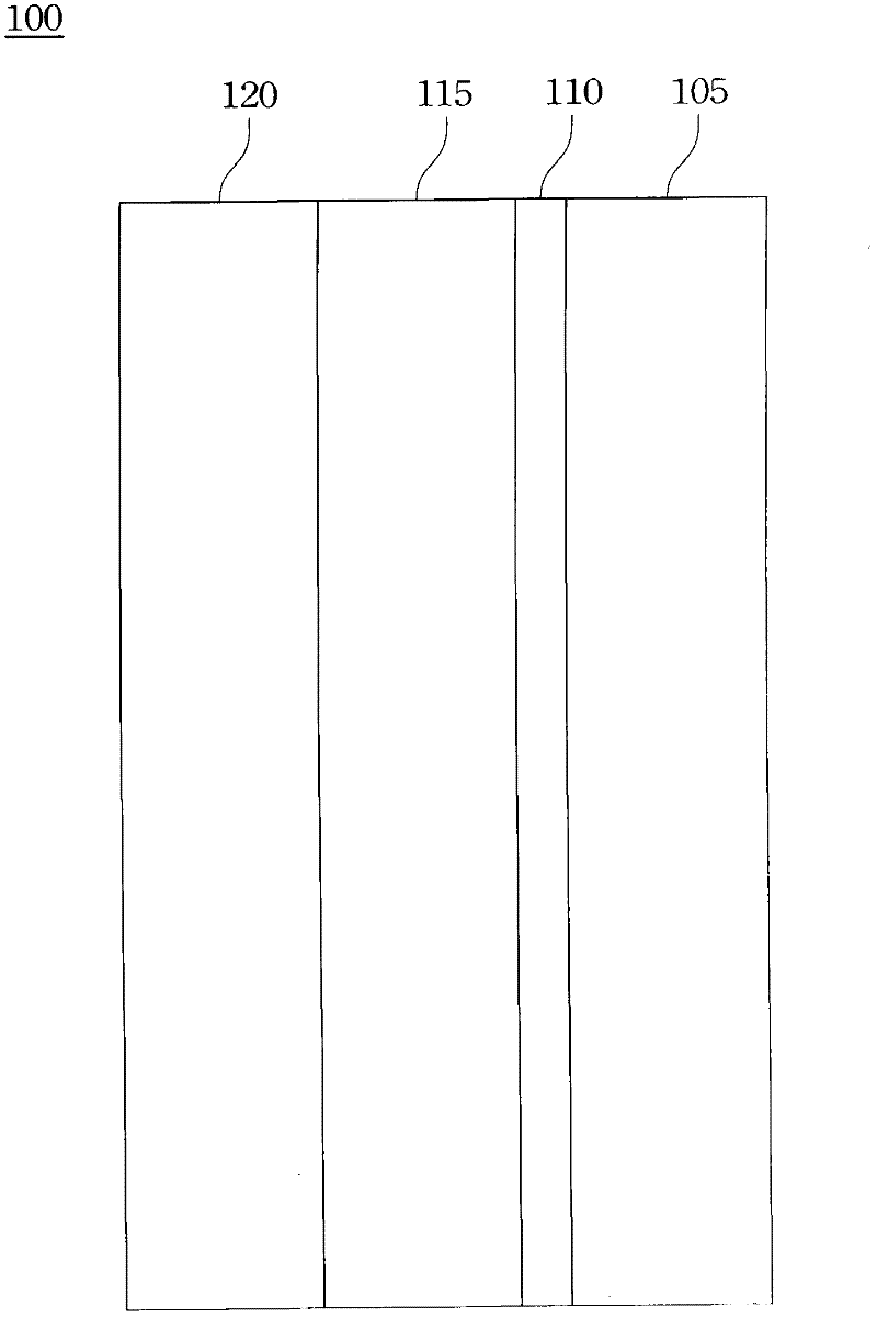
[0021] According to one embodiment of the present invention, refer to figure 1 , the backplane 100 includes: a dielectric layer 105 , an adhesive layer 110 , a barrier layer 115 and a weath...
PUM
| Property | Measurement | Unit |
|---|---|---|
| thickness | aaaaa | aaaaa |
| diameter | aaaaa | aaaaa |
| thickness | aaaaa | aaaaa |
Abstract
Description
Claims
Application Information