Eureka AIR delivers breakthrough ideas for toughest innovation challenges, trusted by R&D personnel around the world.

Improved film thickness measurement

A film thickness and thin film technology, applied in the direction of measuring devices, instruments, caliper sensors, etc., can solve time-consuming problems and achieve the effect of improving the measurement speed

Inactive Publication Date: 2012-05-16
PILKINGTON GROUP LTD
View PDF8 Cites 8 Cited by
  • Summary
  • Abstract
  • Description
  • Claims
  • Application Information

AI Technical Summary

Problems solved by technology

This method is time consuming because in addition to measuring the sample thickness, the thickness of a reference sample must also be measured

Method used


Image

  • Improved film thickness measurement
  • Improved film thickness measurement
  • Improved film thickness measurement

Examples


Embodiment Construction

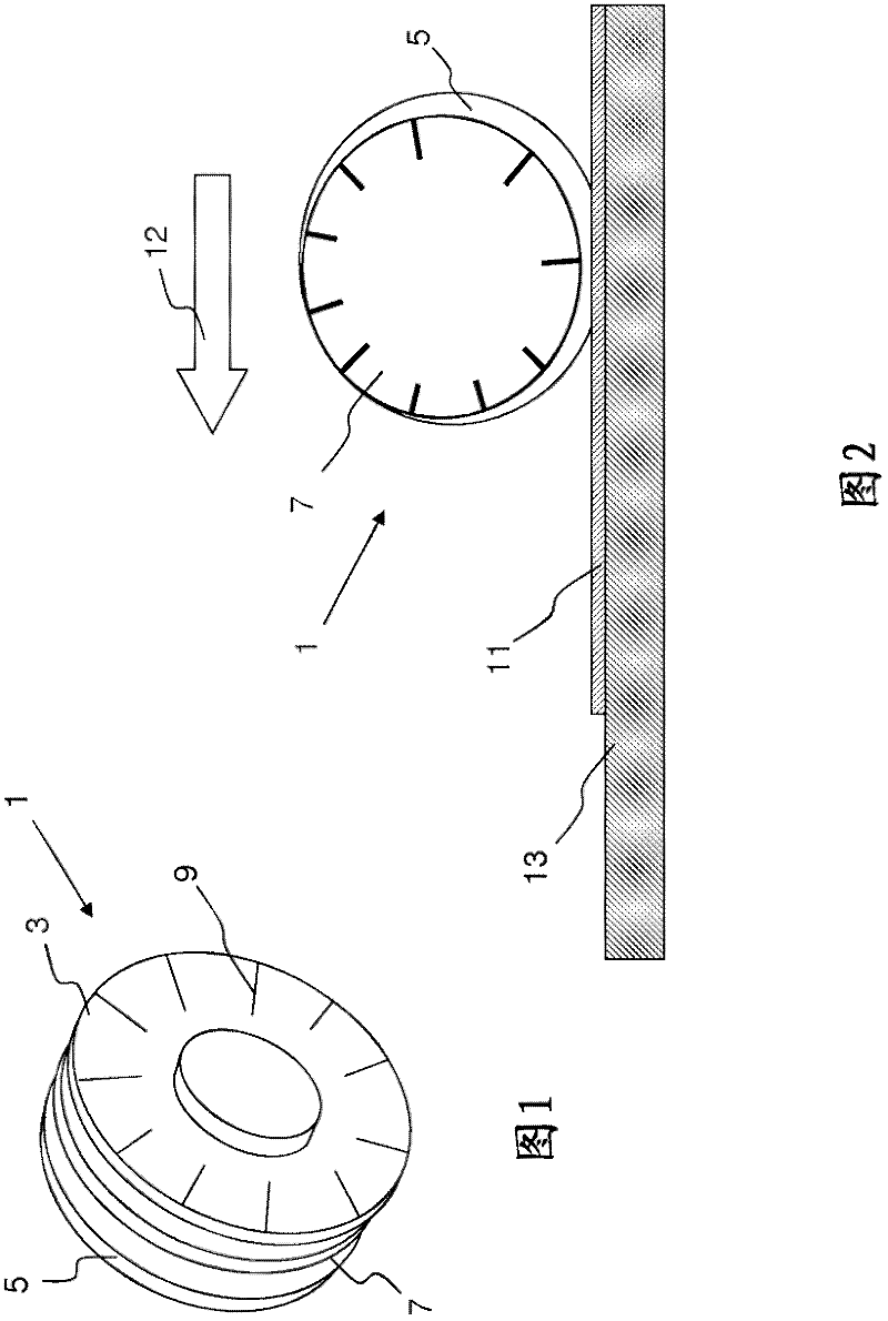
[0047] figure 1 A perspective view of a wheel for measuring wet ink thickness on a flat glass substrate in a manner known to those skilled in the art is shown. The wheel 1 comprises three metal discs, two outer discs 3 , 5 and one inner disc 7 . The outer discs 3, 5 are concentric and have the same outer diameter. The inner discs are smaller than the outer discs 3, 5 and are arranged concentrically with respect to the outer discs. The outer diameter of the inner disc 7 coincides at one point with the outer diameters of the two outer discs. On the outer disc 3 there is a calibration scale 9 .

[0048] refer to figure 2 , the thickness of the wet ink film 11 on the flat glass plate 13 is determined using the wheel 2 in the following manner. First, the wheel is placed on the glass plate 13 so that the wheel 1 contacts the wet ink film 11 . The wheel then rolls in the direction of arrow 12 . As the wheel rolls past the wet ink film, the inner disc 7 will eventually contact...


PUM


Abstract

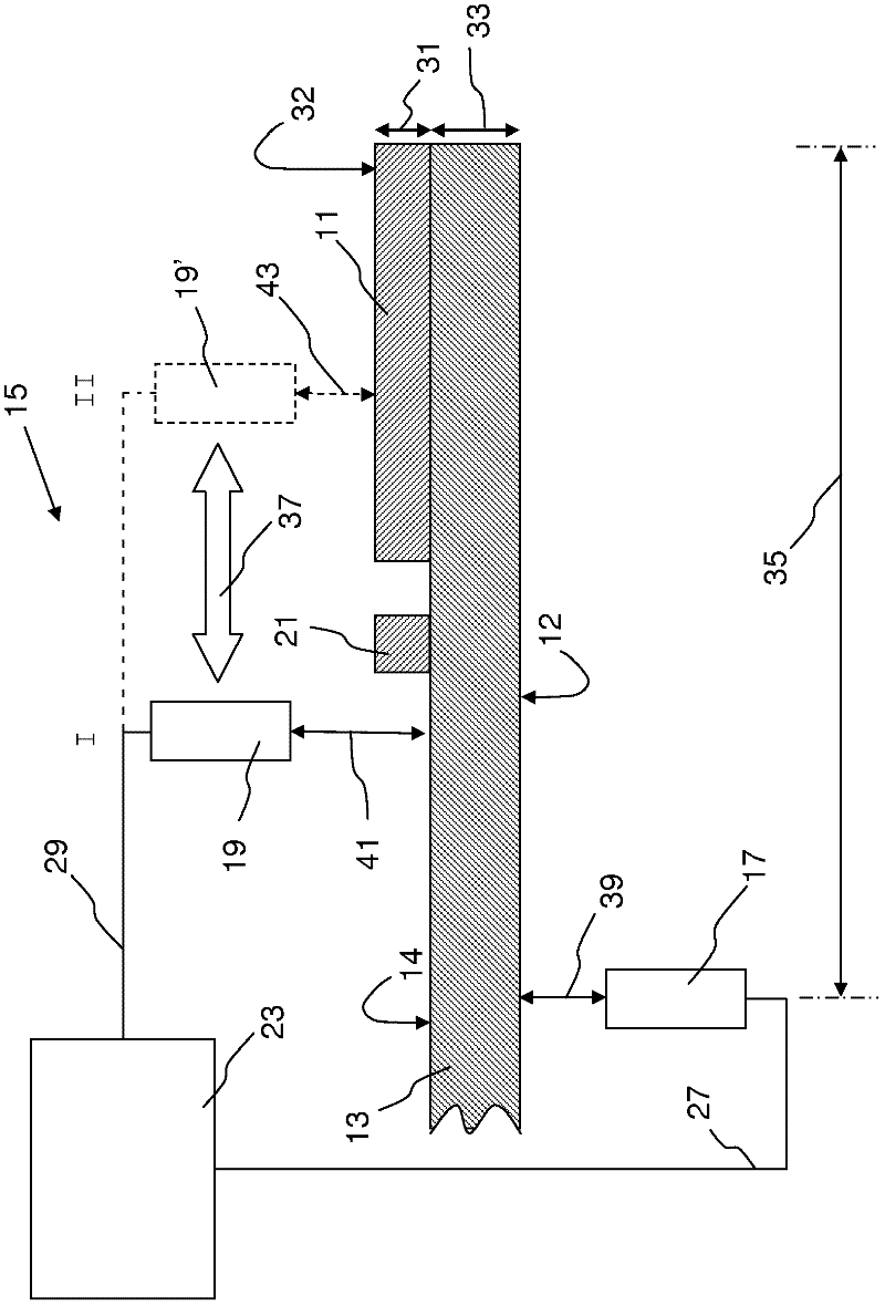
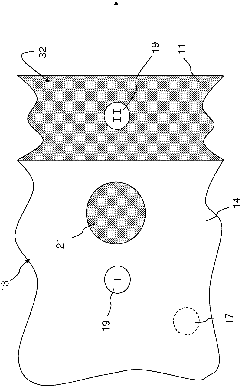
A method for determining the thickness of a film on a substrate is described. The substrate has a first major surface opposite a second major surface, and the film covers a portion of the first major surface. During a first measurement step, a first measuring beam is used to determine the distance from a first reference point to a portion of the first major surface of the substrate that is not covered with the film,and a second measuring beam is used to determine the distance from a second reference point to a portion of the second major surface of the substrate that is not covered with film. During a second measurement step the first measuring beam is used to determine the distance from the first reference point to the film, and the second measuring beam is used to determine the distance from the second reference point to a portion of the second major surface of the substrate that is not covered with film. The thickness of the film so determined may be used as a control parameter in a method of applying an ink to an automotive glazing pane.

Description

technical field [0001] The present invention relates to a method for determining the thickness of a film on a substrate, in particular the thickness of a wet ink film on a glass plate. Background technique [0002] The use of black masking strips on vehicle windows is known in the automotive industry. Such masking bands are typically formed by applying suitable inks to the flat glass sheet before the glass sheet is subsequently processed. The ink is typically applied to the flat glass plate by a screen printing process, although other suitable techniques may be used, such as inkjet printing, spraying or brushing. The flat glass sheet with wet ink on the major surface is then heated to bend and / or toughen the glass sheet so that the ink is dried and fused to the glass surface. [0003] Depending on the particular application, the ink employed may be conductive or non-conductive. [0004] In the automotive industry, conductive inks are employed in vehicle glazing and in sha...

Claims


Application Information

Patent Timeline
Patent Type & Authority Applications(China)
IPC IPC(8): B05B12/00G01B11/06G01B11/02
CPCG01B11/0616G01B2210/44
Inventor J·S·马萨
Owner PILKINGTON GROUP LTD
Why Eureka
Eureka Blog
Learn More