Siwing-bucket-rotor for centrifugal separator, and centrifugal separator
A centrifuge and rotor technology, applied in the centrifuge and other directions, can solve the problems of prolonging the maintenance cycle, reducing friction, sample damage, etc., and achieve the effect of smooth swinging of the bucket, reducing frictional resistance, and reducing surface pressure
- Summary
- Abstract
- Description
- Claims
- Application Information
AI Technical Summary
Problems solved by technology
Method used
Image
Examples
Embodiment 1
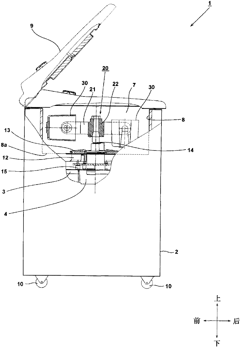
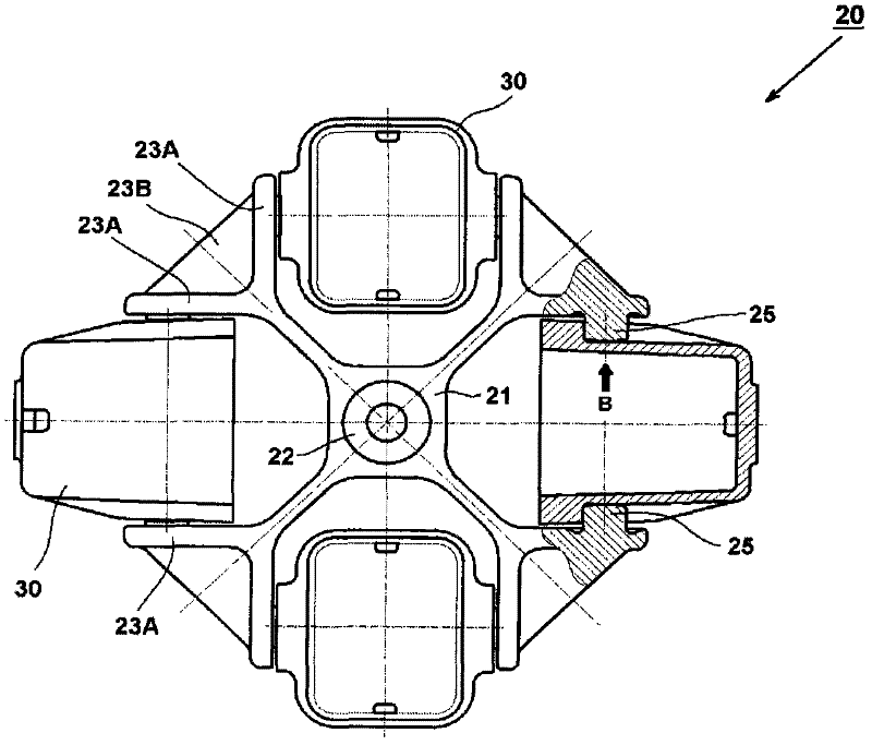
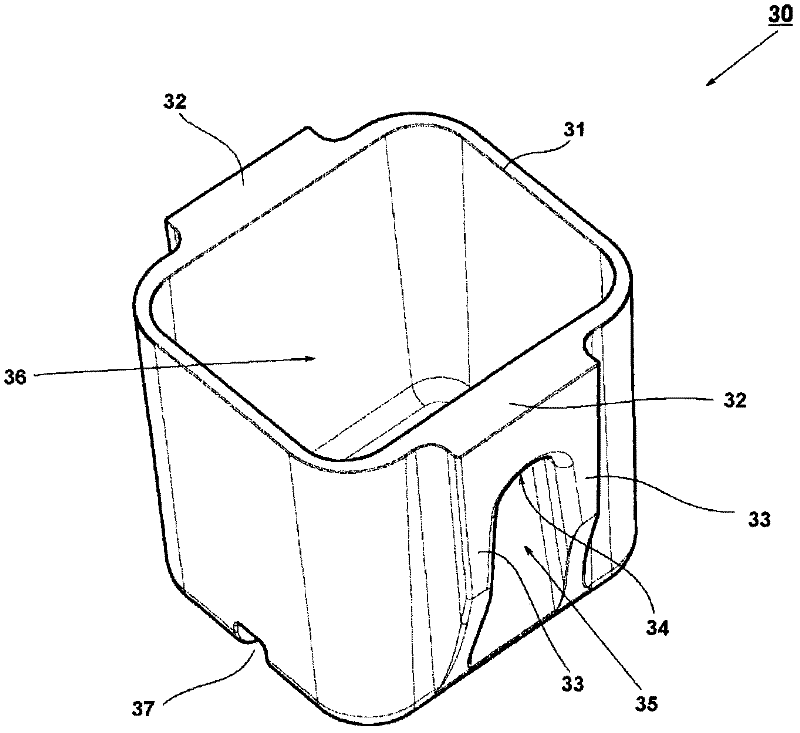
[0044] Embodiments of the present invention will be described below with reference to the accompanying drawings. In addition, in the following drawings, the same reference numerals are assigned to the same parts, and overlapping descriptions are omitted. In addition, in this specification, the front-back and up-down directions are described using the directions shown in the drawings. figure 1 It is a side view showing the centrifuge 1 according to the embodiment of the present invention, and a part thereof is shown in cross-sectional view. exist figure 1 In the figure, in order to facilitate the understanding of the state of the bucket when the rotor stops and rotates, the state of the bucket 30 when it rotates (the bucket 30 on the left in the figure) and the state of the bucket 30 when it stops (the bucket 30 on the right in the figure) are shown in the figure. ) of these two states.
[0045] The centrifuge 1 includes a swing rotor 20 and a motor 4 as a drive device for r...
Embodiment 2
[0065] Next, use Figure 10 The shape of the sliding portion 55A according to the second embodiment of the present invention will be described. Figure 10 It is a development view in which the size of 360 degrees is developed clockwise from the circumferential position A of the sliding portion 55A according to the second embodiment into a planar shape. In the second embodiment, the axial width of the sliding part is the smallest at the circumferential position C (the outermost circumferential position) of the sliding part 55A, and the axial width of the sliding part is the smallest at the circumferential position A (the innermost circumferential position). maximum. A region in contact with the bucket 30 of the sliding portion 55A is a shaded portion 57 . Here, the width in the axial direction is constant from the circumferential position A1 to the circumferential position A2. In order to make the axial width from the circumferential position A1 to the circumferential positi...
Embodiment 3
[0067] Use below Figure 11 The shape of the sliding portion 65A according to the third embodiment of the present invention will be described. Figure 11 It is a development view in which the sliding portion 65A according to the third embodiment is developed in a planar shape in a clockwise direction by 360 degrees from the circumferential position A. In the third embodiment, the axial width of the sliding portion 65A is the smallest at the circumferential position C (the outermost circumferential position) of the sliding portion 65A, and the axial width of the sliding portion is the smallest at the circumferential position A (the innermost circumferential position). Maximum width. A region in contact with the bucket 30 of the sliding portion 65A is a shaded portion 67 . In addition, from the circumferential position A1 to the circumferential position A2, the axial width is not fixed. Since the axial width is the largest at the circumferential position A, the shape and struc...
PUM
 Abstract
Description
Claims
Application Information
 - R&D
- Intellectual Property
- Life Sciences
- Materials
- Tech Scout
- Unparalleled Data Quality
- Higher Quality Content
- 60% Fewer Hallucinations
Browse by: Latest US Patents, China's latest patents, Technical Efficacy Thesaurus, Application Domain, Technology Topic, Popular Technical Reports.
© 2025 PatSnap. All rights reserved.Legal|Privacy policy|Modern Slavery Act Transparency Statement|Sitemap|About US| Contact US: help@patsnap.com


