Method for controlling a hybrid drive train of a vehicle

一种动力系统、控制方法的技术,应用在混合动力车辆、道路车辆驱动控制系统、传动装置控制等方向,能够解决降低行驶舒适感等问题

Inactive Publication Date: 2012-05-23
ZF FRIEDRICHSHAFEN AG
View PDF7 Cites 17 Cited by
  • Summary
  • Abstract
  • Description
  • Claims
  • Application Information

AI Technical Summary

Problems solved by technology

However, since the separating clutch is always continuously engaged during traction and high speed rotation of the internal combustion engine, the torque peaks and speed peaks arising from the adjustment process of the internal combustion engine and from the separating clutch are continuously transmitted to the rotor of the electric machine and are From this rotor, at least partially via the friction shifting element to be disconnected, it is guided into the powershift transmission, thereby reducing driving comfort and increasing wear on the gears and bearings of the powershift transmission

Method used


Image

  • Method for controlling a hybrid drive train of a vehicle
  • Method for controlling a hybrid drive train of a vehicle
  • Method for controlling a hybrid drive train of a vehicle

Examples


Embodiment Construction

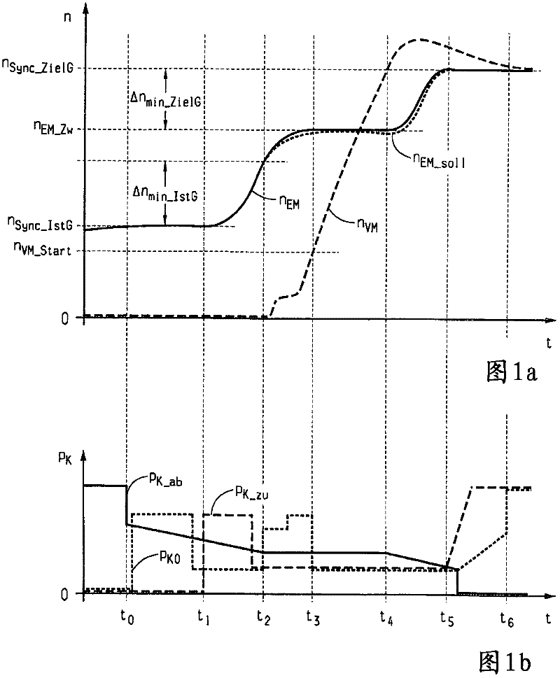
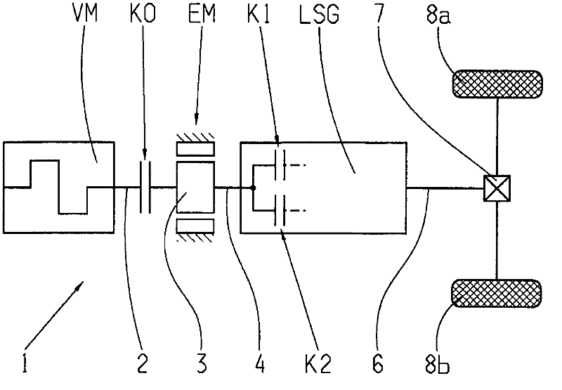
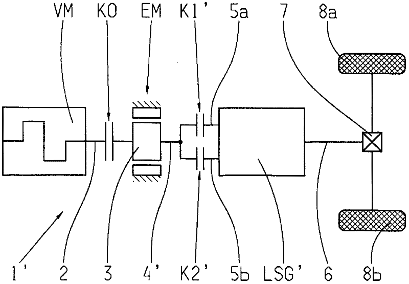
[0030] exist Figure 2a and Figure 2b A hybrid power system 1 , 1 ′ working in parallel is schematically shown in FIG. 1 , and the control method according to the present invention can be applied to the hybrid power system. The two embodiments of the hybrid drive system 1, 1' each comprise: an internal combustion engine VM equipped with a drive shaft 2; an electric machine EM operable at least as a motor and equipped with a rotor 3; and a powershift transmission LSG , LSG'. The rotors 3 of the electric machine EM can be connected to and decoupled from the drive shaft 2 of the internal combustion engine VM via an automated separating clutch K0, so that the internal combustion engine can, if necessary, be started via the electric machine EM, coupled to it and Disconnect the motor. The rotor 3 of the electric machine EM is connected on the output side to an input element 4 , 4 ′ of a powershift transmission LSG, LSG′, respectively.

[0031] in press Figure 2a In the illust...


PUM


Abstract

A method of controlling a hybrid drive-train of a vehicle in which the hybrid drive-train comprises a combustion engine having a driveshaft, an electric machine that can be connected to the driveshaft of the engine by a clutch, an automated transmission with an input which is connected to the rotor of the electric machine, and shifting elements for shifting between two gears. During electric driving operation with the engine stopped and the clutch disengaged, the engine can be drag-started in combination with a downshift in the transmission. Drag starting of the engine is carried out by disengaging the frictional shifting element to be disengaged to below a slipping limit, engaging the clutch until the engine reaches or exceeds its minimum starting speed, starting the engine self-starts, substantially disengaging the clutch, separately adjusting the engine and electric machine to the synchronous speed of the target gear, and fully engaging and disengaging associated shifting elements.

Description

technical field [0001] The invention relates to a method for controlling a hybrid powertrain of a motor vehicle, the hybrid powertrain comprising: an internal combustion engine with a drive shaft; an electric machine operable at least as a motor, the electric machine comprising a drive shaft that can be connected to the internal combustion engine via an automated separation clutch Connected rotors; automated powershift transmissions comprising an input element in driving connection with a rotor of an electric machine and comprising at least two friction shifting elements for temporally overlapping transitions between two transmission gears, In this case, during electric driving operation with the internal combustion engine switched off and the release clutch disengaged, the internal combustion engine is started in traction-start mode in conjunction with a downshift of the powershift transmission. Background technique [0002] Parallel-operating hybrid powertrains of the abov...

Claims


Application Information

Patent Timeline
Patent Type & Authority Applications(China)
IPC IPC(8): B60W20/00B60W10/02B60W10/06B60W10/08B60W10/10
CPCB60W20/00Y02T10/6286B60W10/113B60W30/192B60Y2300/49B60W10/06B60K6/48B60W10/02F16H2061/0422B60W10/08Y02T10/6221Y02T10/62B60W20/40B60W2710/021
Inventor P·席勒K·施泰因豪泽B·阿尔盖尔
Owner ZF FRIEDRICHSHAFEN AG
Why Eureka
Try Eureka