Control method for a transmission with hydraulic system comprising a variable displacement pump

a control method and hydraulic system technology, applied in the direction of gearing control, gear lubrication/cooling, gearing elements, etc., can solve the problems of different transmission components and/or electric components of automatic transmissions, and achieve the effect of short operating times and high efficiency

Active Publication Date: 2019-05-14
ZF FRIEDRICHSHAFEN AG
View PDF14 Cites 2 Cited by
  • Summary
  • Abstract
  • Description
  • Claims
  • Application Information

AI Technical Summary

Benefits of technology

[0014]Via the method according to the invention, disadvantageous operating state progressions of this type are avoidable in a simple way by setting, in a manner adapted to the respectively currently prevailing hydraulic fluid temperature, of the hydraulic fluid volume flow which is conveyed by the hydraulic pump and the resulting hydraulic fluid volume flow which flows through the heat exchanger, or are changeable within short operating times in such a way that thermally induced transmission damage does not occur and high driving comfort is achieved.
[0015]In one advantageous variant of the method according to the invention, the delivery volume flow of the hydraulic pump is varied in a manner dependent on a current heat output of the heat exchanger, that is to say in each case in a manner dependent on the heat or cooling output of the heat exchanger. If a high heat output of the heat exchanger prevails, there is therefore the possibility, with low complexity, to raise the delivery volume of the hydraulic pump to a relatively small extent and, as a result, to be able to operate the transmission with a higher efficiency than is the case at low available heat outputs of the heat exchanger.
[0016]In one variant of the method according to the invention which can be carried out in a particularly simple manner, the delivery volume flow of the hydraulic pump is raised if a temperature threshold is exceeded in order for it to be possible to avoid overheating operating states of the transmission.
[0023]In general, the procedure according to the invention achieves a situation where temperature control of the hydraulic fluid of a transmission can be carried out to a desired extent during energy-optimized operating states, overheating operating states of a transmission is avoidable, and the hydraulic fluid temperature can be brought within short operating times to an operating temperature at which the transmission is operable with a high efficiency.
[0024]Here, for example, in order to protect the oil sump against overheating, what is known as a cooler cooling oil requirement or a hydraulic fluid volume flow, which is to be guided through the heat exchanger by the vane cell pump, is set in a manner dependent on the transmission oil temperature, which makes it possible for the necessary cooling output of the cooling system to be utilized for the transmission cooling.

Problems solved by technology

During operating state progressions of this type of an automatic transmission, there is then the possibility that the hydraulic fluid volume of the automatic transmission reaches impermissibly high temperatures which cause irreversible impairments of the functionality of different transmission components and / or electric components of the automatic transmission, which is undesirable, however.

Method used


Image

  • Control method for a transmission with hydraulic system comprising a variable displacement pump
  • Control method for a transmission with hydraulic system comprising a variable displacement pump
  • Control method for a transmission with hydraulic system comprising a variable displacement pump

Examples


Embodiment Construction

[0032]Reference will now be made to embodiments of the invention, one or more examples of which are shown in the drawing. Each embodiment is provided by way of explanation of the invention, and not as a limitation of the invention. For example, features illustrated or described as part of one embodiment can be combined with another embodiment to yield still another embodiment. It is intended that the present invention include these and other modifications and variations to the embodiments described herein.

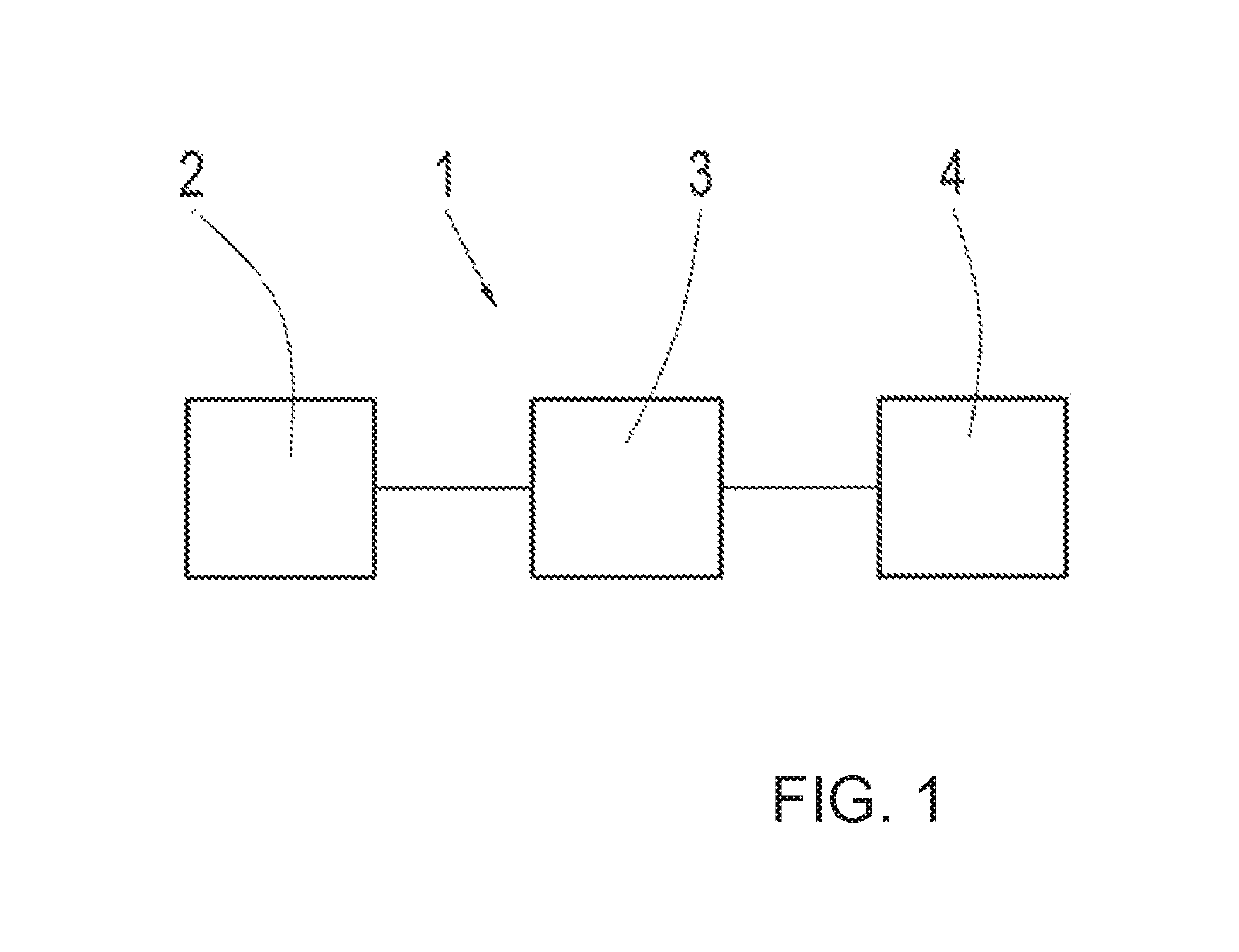
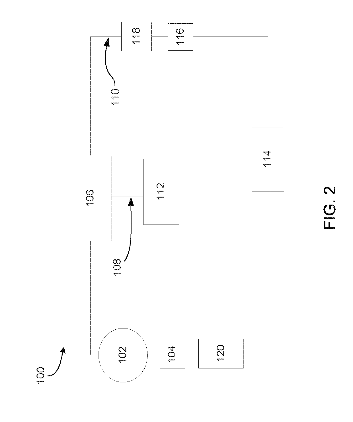
[0033]FIG.1 shows a schematic illustration of a vehicle drive train 1 with a drive machine 2, a transmission 3 configured as a double clutch transmission, and an output 4, the transmission 3 being operatively connected on the input side to the drive machine 2 and on the output side to the output 4. The transmission 3 is configured with an electrohydraulic transmission system or a hydraulic system 100, shown in FIG. 2, which includes a pressure medium source which is configured in t...


PUM


Abstract

A method for operating a transmission (3) with a hydraulic system comprising a variable capacity hydraulic pump, the method comprising determining during operation, a current hydraulic fluid volume requirement for actuating the transmission (3) and for temperature controlling and lubricating components of the transmission (3); setting the delivery volume of the hydraulic pump in a manner dependent on the currently determined hydraulic fluid volume requirement of the transmission (3), the delivery volume of the hydraulic pump, provided for temperature controlling and lubricating the components, being guided at least partially through a heat exchanger; wherein the delivery volume of the hydraulic pump is varied in a manner dependent on a temperature of the hydraulic fluid to an extent which sets that part of the delivery volume flow of the hydraulic pump which is to be guided via the heat exchanger.

Description

FIELD OF THE INVENTION[0001]The invention relates generally to a method for operating a transmission with a hydraulic system which includes a variable displacement hydraulic pump.BACKGROUND[0002]Automatic transmissions known from practice are often configured with what is known as a fixed displacement pump for hydraulic supply, the delivery volume of which fixed displacement pump is proportional to an input speed. This means that the delivery volume of the fixed displacement pumps increases continuously as the input speed rises. Here, the fixed displacement pumps are usually operatively connected via a transmission input shaft to a drive machine of a vehicle drive train, and are therefore driven proportionally with respect to the input speed of the drive machine.[0003]In order to avoid undersupplied operating states of the transmission over the entire operating range of a transmission, at least in the range of the transmission actuator system, the delivery capacity of fixed displace...

Claims


Application Information

Patent Timeline
Patent Type & Authority Patents(United States)
IPC IPC(8): F16H57/04F16H61/00
CPCF16H57/0446F16H57/0413F16H57/0436F16H61/0025F16H57/0417F16H2061/0037
Inventor TERWART, MARKUSNOVAK, RAINERFRIEDERICH, DIRKSPATH, LUKAS
Owner ZF FRIEDRICHSHAFEN AG
Why Eureka
Try Eureka