drive system for vehicles

A drive system, vehicle technology, applied in vehicle components, fluid drive clutches, non-mechanical drive clutches, etc., can solve the problems affecting the operation responsiveness of the clutch mechanism, the influence of the operation responsiveness, the influence of centrifugal hydraulic pressure, etc.

Inactive Publication Date: 2015-09-16
AISIN SEIKI KK
View PDF8 Cites 0 Cited by
  • Summary
  • Abstract
  • Description
  • Claims
  • Application Information

AI Technical Summary

Problems solved by technology

[0003] According to the drive systems disclosed in each of Patent Documents 1, 2 and 3, under the condition that the input shaft of the transmission is rotating, when the clutch mechanism is brought into the connected state or into the disengaged state, the hydraulic pressure (hereinafter due to the centrifugal force of the rotation) The hydraulic pressure caused by the rotating centrifugal force is called centrifugal hydraulic pressure), which will affect the operational responsiveness of the clutch mechanism when the clutch mechanism switches between the connected state and the separated state
As a result, the improvement of the operational responsiveness of the clutch mechanism may be limited
In addition, centrifugal hydraulic pressure due to rotation is affected by the rotational speed of the input shaft
According to this, the operational responsiveness of the clutch mechanism is affected by the moving speed of the vehicle, thereby limiting the improvement of the operational responsiveness of the clutch mechanism

Method used


Image

  • drive system for vehicles
  • drive system for vehicles
  • drive system for vehicles

Examples


Embodiment Construction

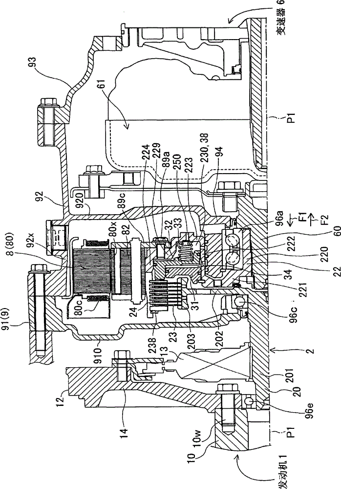
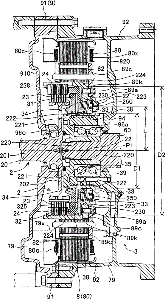
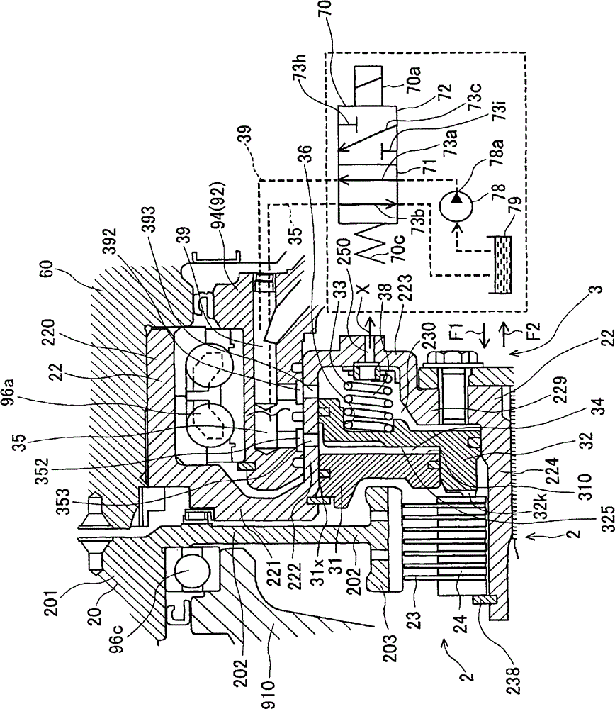
[0026] The first embodiment of the present invention is applied to a hybrid vehicle, for example, a hybrid passenger vehicle, a large hybrid vehicle, and the like. Next, a first embodiment of the present invention will be described with reference to the drawings. figure 1 is a sectional view illustrating the upper half of the drive system for a vehicle according to the first embodiment. figure 2 is a sectional view illustrating a portion near the clutch mechanism 2 in the drive system according to the first embodiment. image 3 and Figure 4 Each is an enlarged view illustrating a main part of the lower half of the drive system according to the first embodiment. Figure 5 is a block diagram of the drive system according to the first embodiment. Such as Figure 5As shown in , the drive system includes: an engine 1 as a drive source, a clutch mechanism 2, a drive motor 8 (hereinafter referred to as an electric motor) formed by an electric motor (electric motor) for driving ...


PUM


Abstract

A drive system for a vehicle includes an engine, a transmission, a clutch mechanism including first and second clutch portions, the clutch mechanism being switchable between connected and disconnected states, and a clutch operation mechanism switching the clutch mechanism between the connected and disconnected states, the clutch operation mechanism including a clutch drum forming a drum chamber, a piston dividing the drum chamber into a spring chamber and a pressurizing chamber, a control valve, a biasing member arranged in the spring chamber and exerting a biasing force in a direction in which the first and second clutch portions are engaged with each other, and a bore formed in the clutch drum, the bore discharging oil of the spring chamber to an outer side of the spring chamber in a state where a counteracting force against a centrifugal force acting in the pressurizing chamber is generated in the spring chamber.

Description

technical field [0001] The invention relates to a drive system for a vehicle. Background technique [0002] In JP2009-101730A, JP2006-137406A, and JP2010-6190A (hereinafter referred to as Patent Documents 1, 2, and 3), each discloses a well-known drive system for a vehicle including a transmission (the engine driving force from the engine output shaft is transmitted to the transmission) and a clutch mechanism arranged between the output shaft of the engine and the input shaft of the transmission. According to the drive systems disclosed in each of Patent Documents 1, 2 and 3, the clutch mechanism includes a first clutch portion arranged at an engine output shaft, and a second clutch portion arranged at a transmission input shaft. The clutch mechanism can be switched between a connected state and a disconnected state. In the connected state, the first clutch part and the second clutch part are engaged with each other, thereby transmitting the driving force of the engine to t...

Claims


Application Information

Patent Timeline
Patent Type & Authority Patents(China)
IPC IPC(8): F16D25/062B60K17/02B60K17/06
CPCF16D25/0638F16D48/02F16D2048/0272F16D2048/0233F16D2048/0269
Inventor 池田实伊藤真一
Owner AISIN SEIKI KK
Why Eureka
Try Eureka