Circuit and method for controlling power converter in current mode

A technology for controlling power supply and control circuit, which is used in control/regulation systems, output power conversion devices, DC power input conversion to DC power output and other directions, and can solve problems such as complex parameter recommendation tables.

Inactive Publication Date: 2012-05-23
RICHTEK TECH
View PDF5 Cites 9 Cited by
  • Summary
  • Abstract
  • Description
  • Claims
  • Application Information

AI Technical Summary

Problems solved by technology

Since the inductance L and compensation parameters have to be changed under different input voltage and output voltage conditions, the existing parameter recommendation tables for current mode control power converters are relatively complicated.

Method used


Image

  • Circuit and method for controlling power converter in current mode
  • Circuit and method for controlling power converter in current mode
  • Circuit and method for controlling power converter in current mode

Examples


Embodiment Construction

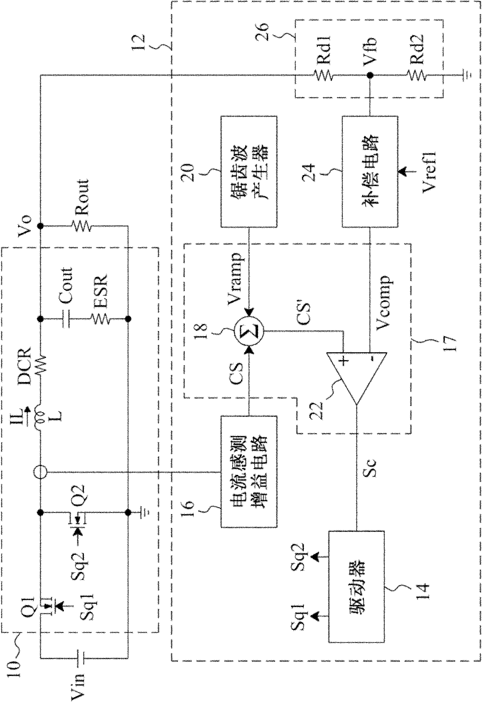
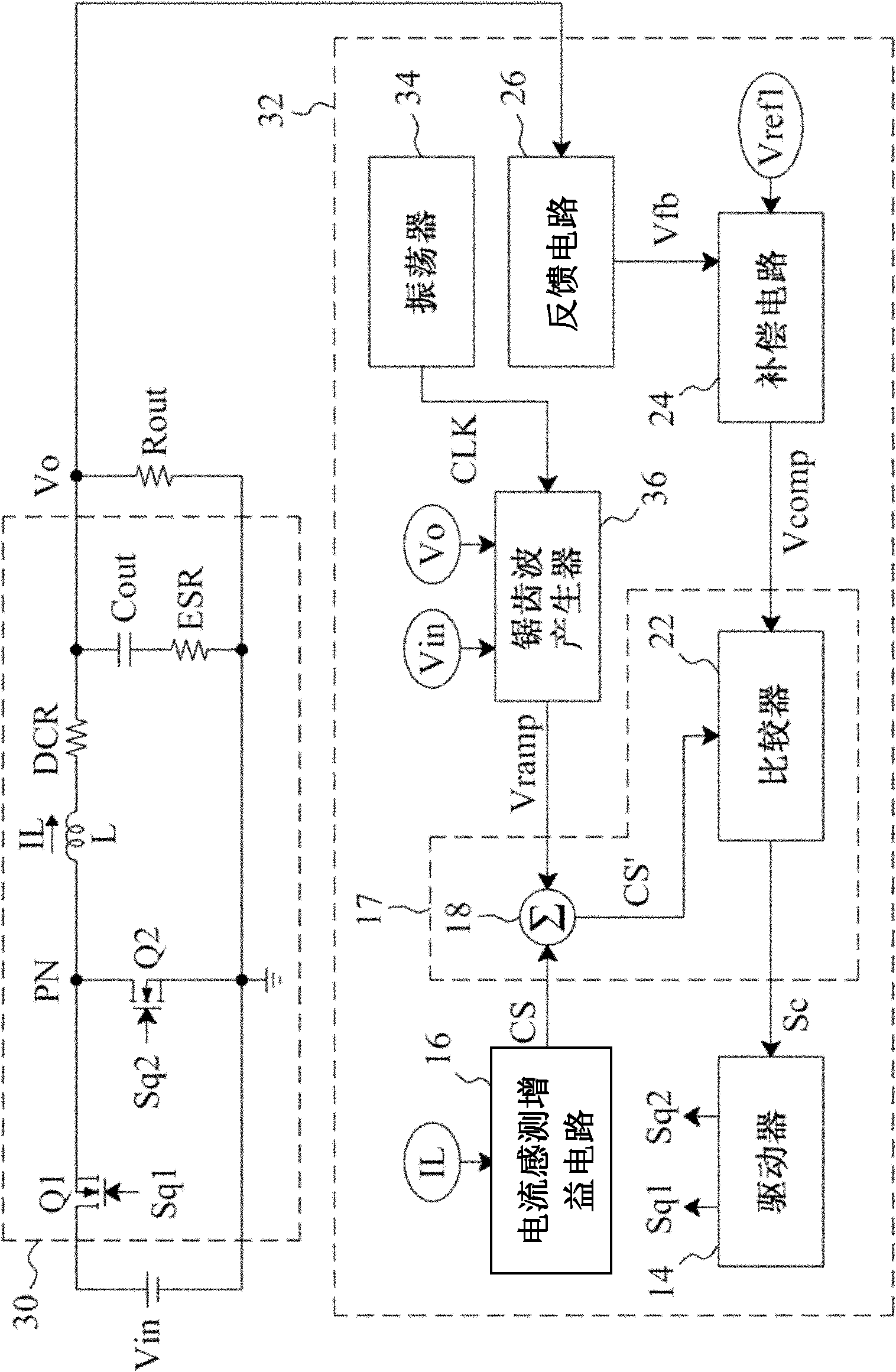
[0048] figure 2 It is a current mode control step-down power converter using the control circuit of the present invention, which includes a step-down switching regulator 30 for converting the input voltage Vin into an output voltage Vo, and the control circuit 32 provides control signals Sq1 and Sq2 to drive Switching regulator 30. The switching regulator 30 includes a power switch Q1 connected between the input terminal Vin and the phase node PN, controlled by the control signal Sq1; a power switch Q2 connected between the phase node PN and the ground terminal GND, controlled by the control signal Sq2; The inductor L is connected between the phase node PN and the output terminal Vo; and the capacitor Cout is connected between the output terminal Vo and the ground terminal GND. control circuit 32 with figure 1 The control circuit 12 also has a driver 14, a current sensing gain circuit 16, a modulator 17, a compensation circuit 24, and a feedback circuit 26. In addition, the...


PUM


Abstract

The invention discloses a circuit and a method for controlling a power converter in a current mode. The circuit comprises a feedback circuit, a compensation circuit, a current sensing gain circuit, a sawtooth wave generator, a modulator, and a driver, wherein the feedback circuit is used for detecting output voltage to generate a feedback signal; the compensation circuit is connected with the feedback circuit and is used for amplifying the difference between the feedback signal and reference voltage to generate a first signal; the current sensing gain circuit is used for detecting inductive current of an inductor to generate a second signal; the sawtooth wave generator is used for providing sawtooth wave signals and determining a peak value or a valley value of the sawtooth wave signals according to at least one of an input voltage related signal and an output voltage related signal; the modulator is connected with the compensation circuit, the current sensing gain circuit and the sawtooth wave generator and is used for generating a third signal according to the first and second signals; and the driver is connected with a comparator and is used for generating a control signal according to the third signal to switch a power switch. Under different input voltage and output voltage conditions, the same inductor can be used, the parameters of the compensation circuit are not required to be changed, and the subharmonic of the output voltage can be avoided.

Description

technical field [0001] The present invention relates to a power converter, in particular to a current mode control power converter. Background technique [0002] The input voltage and output voltage conversion ratio of the current mode control power converter will affect the output duty cycle of the control circuit. When the duty cycle is greater than 50%, the power converter may have sub-harmonic conditions. This will cause severe instability of the power converter, which will affect the abnormal operation of the load. Therefore, the current mode control power converter will add a sawtooth signal to avoid the occurrence of sub-harmonics. [0003] figure 1 It is an existing current mode control step-down power converter, which includes a step-down switching regulator 10 for converting the input voltage Vin into an output voltage Vo, and a control circuit 12 that provides control signals Sq1 and Sq2 to drive the step-down Switching regulator 10. The control circuit 12 incl...

Claims


Application Information

Patent Timeline
Patent Type & Authority Applications(China)
IPC IPC(8): H02M3/158H02M1/14
Inventor 陈文玮刘国基
Owner RICHTEK TECH
Why Eureka
Try Eureka