Cutting method for steel for use in machine structure

一种机械结构、切削方法的技术,应用在用于车床的刀具、金属加工机械零件、车削设备等方向,达到工具寿命优良的效果

Inactive Publication Date: 2012-05-23
NIPPON STEEL CORP
View PDF9 Cites 39 Cited by
  • Summary
  • Abstract
  • Description
  • Claims
  • Application Information

AI Technical Summary

Problems solved by technology

However, there is a problem that Pb is an environmental load substance

Method used


Image

  • Cutting method for steel for use in machine structure
  • Cutting method for steel for use in machine structure
  • Cutting method for steel for use in machine structure

Examples


Embodiment

[0144] Next, examples will be given to specifically describe the effects of the present invention.

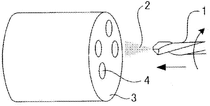
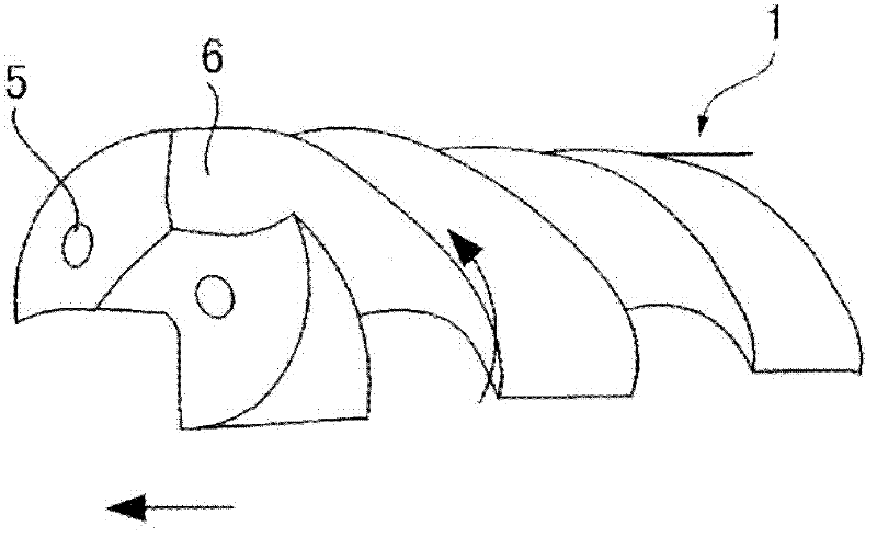
[0145] In this example, 150 kg of steel having the compositions shown in Tables 1 to 5 were smelted in a vacuum melting furnace, and then the obtained steel was forged into a cylindrical shape with a diameter of 50 mm at a temperature of 1250° C. , performing a homogenization treatment of heating at 1300° C. for 2 hours and then air cooling, and then performing a heat treatment of heating at 1200° C. for 1 hour and then air cooling. Then, a test piece for tool life evaluation with a diameter of 48 mm and a length of 105 mm was cut out from the obtained steel material, and the test piece was used for a test (test Nos. A1 to E12).
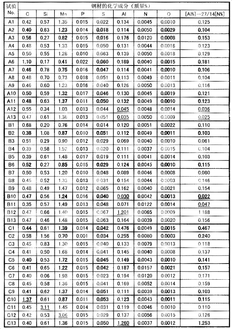
[0146] Table 1

[0147]

[0148] * Table 2 shows other elements.

[0149] * In Test Nos. A1 to C12, Sb, Sn, Zn, B, Te, Se, Bi, Pb, Li, Na, K, Ba, and Sr were not added to the steel as other elements.

[0150] * Underlines in the table indicat...


PUM

PropertyMeasurementUnit
composition ratioaaaaaaaaaa
diameteraaaaaaaaaa
diameteraaaaaaaaaa

Abstract

In the disclosed cutting method for steel for use in a machine structure, a cutting oil that is supplied at a supply rate of 0.01-200 ml / hour, and an oxidizing gas comprising 21-50% oxygen by volume are mixed together to form a mist, and steel is cut while the mist is sprayed onto the surface of a blade tip of a tool and the surface of the steel. The steel comprises, by mass percentage, 0.01-1.2% C, 0.005-3.0% Si, 0.05-3.0% Mn, 0.001-0.2% P, 0.001-0.35% S, 0.002-0.035% N, and 0.05-1.0% Al, with the remainder comprising Fe and unavoidable impurities, O being kept at or below 0.003%, and the Al content [Al%] and N content [N%] being such that [Al%] - (27 / 14)*[N%] is not less than 0.05%.

Description

technical field [0001] The invention relates to a cutting method of steel for machine structure. [0002] This application claims priority based on Japanese Patent Application No. 2010-78231 for which it applied in Japan on March 30, 2010, and uses the content here. Background technique [0003] Due to recent global environmental problems, environmental considerations such as energy saving, resource saving, and reduction of environmental load substances have become indispensable when manufacturing industrial products. The main components of automobiles made of mechanical structural steel, such as gears, CVT (Continuously Variable Transmission), crankshaft, connecting rod, CVJ (Constant Velocity Joint), etc. Structural steel is manufactured by machining. Therefore, even in the field of cutting of steel for machine structural use, from the viewpoint of cutting technology and steel for machine structural use as a material to be cut, it is necessary to study technology that ta...

Claims


Application Information

Patent Timeline
Patent Type & Authority Applications(China)
IPC IPC(8): B23Q11/10B23B1/00B23B47/00B23C5/28C22C38/00C22C38/60
CPCC22C38/002B23B2250/12B23C2250/12C22C38/04C21D1/76C22C38/60B23B35/00C21D1/667C22C38/06C22C38/02C22C38/001B23Q11/1046B23B2222/84C21D2261/00Y10T408/03Y10T408/45Y10T408/44Y10T83/0443Y02P70/10
Inventor 间曾利治宫西庆吉田卓
Owner NIPPON STEEL CORP
Why Eureka
Try Eureka