Vapor supply device

A technology for supplying devices and steam generating devices, applied to steam generating devices, heating devices, steam generation, etc., to achieve the effect of reducing operating costs

Inactive Publication Date: 2012-05-23
IHI CORP
View PDF7 Cites 6 Cited by
  • Summary
  • Abstract
  • Description
  • Claims
  • Application Information

AI Technical Summary

Problems solved by technology

However, the above-mentioned boilers generally do not have the steam generation capacity corresponding to the steam pressure and temperature conditions required by each steam-using facility, and are often commercialized with general-purpose specifications.

Method used


Image

  • Vapor supply device
  • Vapor supply device
  • Vapor supply device

Examples


Embodiment

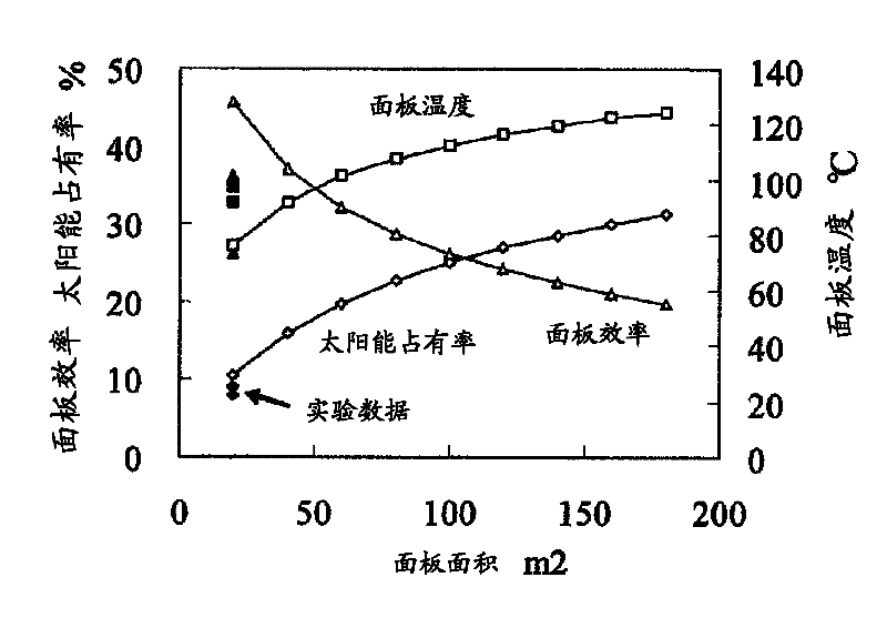
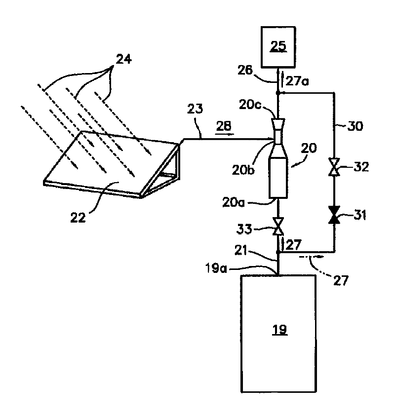
[0101] As an embodiment of the present invention, in Figure 4 said in figure 1 The result of the actual operation of the steam supply device of the embodiment shown. As an example, in the steam supply device for operation, a boiler that burns fossil fuels and generates steam is used as the high-pressure steam generating boiler 19 . This boiler has the capability of generating steam at 180°C and 850kPa. In the solar heat collector 22, a solar heat collector in the form of a heat collecting panel using sunlight is employed. The solar energy 24 is collected by the solar heat collecting panel, and the water inside is heated up. Therefore, in the steam supply device used in the examples, the temperature of the water inside can be detected by measuring the temperature of the solar heat collecting panel.

[0102] exist Figure 4 In , the horizontal axis represents the elapsed time. The elapsed time is displayed in seconds, Figure 4 The indicated operation results represent ...


PUM


Abstract

A vapor supply device is formed by connecting the vapor inlet (20a) of a vapor injector (20) to the vapor outlet (19a) of a high-pressure-vapor generating boiler (19). A solar heat collector (22) is connected to the suction inlet (20b) of the vapor injector (20), and a vapor-using device (25) is connected to the discharge outlet (20c) of the vapor injector. The vapor injector (20) is driven by high-pressure, high-temperature vapor (27) generated by the high-pressure-vapor generating boiler (19), and the pressure at the suction inlet (20b) decreases. Water having a temperature which has been increased by irradiation of the sunlight (24) to the water boils and evaporates within the solar heat collector (22) at a temperature lower than 100 DEG C to generate low-temperature, low-pressure vapor (28), the pressure within the solar heat collector (22) decreasing as the pressure at the suction inlet (20b) is decreased. The vapor (28) is led to the vapor injector (20) and mixed with the high-pressure, high-temperature vapor (27) generated by the high-pressure-vapor generating boiler (19), and as a result, medium-pressure, medium-temperature vapor (27a) is generated. Supplying the vapor (27a) to the vapor-using device (25) reduces the amount of vapor generation by the high-pressure-vapor generating boiler (19).

Description

[0001] This application claims priority based on Japanese Patent Application No. 2009-163385 for which it applied in Japan on July 10, 2009, and uses the content here. technical field [0002] The present invention relates to a steam supply device. More specifically, it relates to a steam supply device used to supply steam (process steam) used in factories, buildings, and the like. Background technique [0003] When steam-using equipment utilizing steam (steam) or its heat is used in a factory or a building, generally a small boiler such as a once-through boiler is widely used as a supply source of steam (process steam). [0004] In steam-using equipment used in factories, buildings, etc., the pressure and temperature conditions required for the supplied steam vary depending on the purpose of using the steam. However, the above-mentioned boilers generally do not have a steam generating capability corresponding to the steam pressure and temperature conditions required by eac...

Claims


Application Information

Patent Timeline
Patent Type & Authority Applications(China)
IPC IPC(8): F22B3/00F22B33/18F24J2/42F24S90/00
CPCY02E10/40F22B1/006F22B33/14F24J2/42F22B3/045F24S90/00G06F16/58G06F3/011G06F3/0325G06T19/006
Inventor 松野伸介三好一雄大塚裕之
Owner IHI CORP
Why Eureka
Try Eureka