Patterning device for generating a pattern in and/or on a layer

A technology of equipment and composition, applied in welding equipment, opto-mechanical equipment, laser welding equipment, etc., can solve the problem of pattern taking too long, and achieve the effect of reducing composition time, increasing cost and reducing time

Inactive Publication Date: 2012-05-23
KONINKLIJKE PHILIPS ELECTRONICS NV
View PDF4 Cites 3 Cited by
  • Summary
  • Abstract
  • Description
  • Claims
  • Application Information

AI Technical Summary

Problems solved by technology

[0005] The disadvantage of the known patterning devices is that it takes too long to generate the pattern

Method used


Image

  • Patterning device for generating a pattern in and/or on a layer
  • Patterning device for generating a pattern in and/or on a layer
  • Patterning device for generating a pattern in and/or on a layer

Examples


Embodiment Construction

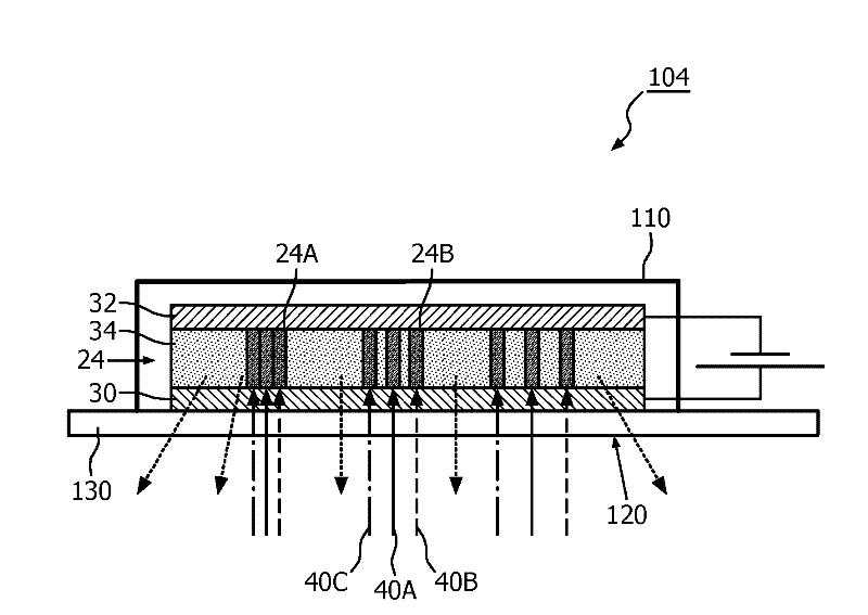
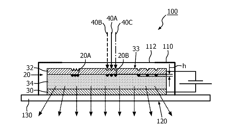
[0044] figure 1 A schematic cross-sectional view of a patterning device 10 according to the invention is shown for producing patterns 20 , 22 , 24 (see FIGS. 4 and 5 ) in and / or on layers 32 , 34 (see FIGS. 4 and 6 ). The patterning apparatus 10 comprises a light source 50 for generating a converging light beam 40 and comprises scanning means 70, eg a movable mirror 70 or a movable exposure chuck 72 on which a substrate comprising layers 32, 34 may be arranged. The patterning device 10 also comprises a diffractive optical element 60 for splitting the concentrated light beam 40 into a plurality of converging beamlets 40A, 40B, 40C. Via a diffractive optical element 60 , the single converging beam 40 is split into a plurality of converging beamlets 40A, 40B, 40C, so that the multiple converging beamlets can be used to generate the patterns 20 , 22 , 24 . In this way, especially when a relatively large area of ​​the pattern 20, 22, 24 comprising areas of substantially equal gray...


PUM


Abstract

The invention relates to a patterning device (10, 12) for generating a pattern (20, 22, 24) in and / or on a layer (32, 34) via a condensed light beam (40). The patterning device comprises a light source (50) for generating the condensed light beam (40), a diffractive optical element (60) for splitting the condensed light beam (40) into a plurality of condensed sub-beams (40A, 40B, 40C) and positioning means (70) for positioning the layer relative to the plurality of condensed sub-beams for generating the pattern. The condensed sub-beams are configured for generating the pattern in and / or on the layer. At least two sub- beams of the plurality of condensed sub-beams comprise substantially equal intensity. An effect of the patterning device according to the invention is that a single condensed light beam is split into a plurality of condensed sub-beams to generate a multi-spot patterning for patterning relatively large areas using the plurality of condensed sub-beams. As such, the patterning time for filling that area in the pattern and for generating the pattern in and / or on the layer is considerably reduced.

Description

technical field [0001] The present invention relates to patterning devices for producing patterns in and / or on layers. Background technique [0002] Patterning devices that use a condensed light beam to create patterns in and / or on layers of a substrate are known in the art. These known patterning devices use, for example, a laser light source to generate a converging light beam. The converging beam has sufficient energy density to, for example, locally damage the layer so that the pattern is visible. Thus, the patterning apparatus includes means for moving a converging beam of light across the surface of the substrate to create or write the pattern. [0003] Organic Light Emitting Diode devices (also known as OLED devices) are considered in many respects to be the future in various lighting applications. They can be used, for example, to create ambient lighting. OLED devices typically include a cathode, an anode, and an emissive organic layer. These parts are typically...

Claims


Application Information

Patent Timeline
Patent Type & Authority Applications(China)
IPC IPC(8): H01L51/50H01L51/00
CPCH01L51/0017G03F7/70383B23K26/0676B23K26/0656B23K26/0853B23K26/066H10K71/231
Inventor C.A.弗舒伦
Owner KONINKLIJKE PHILIPS ELECTRONICS NV
Why Eureka
Try Eureka