Check patentability & draft patents in minutes with Patsnap Eureka AI!

How to assemble the lateral control arm

A technology of assembly position and fastening device, which is applied in the direction of manufacturing tools, transportation and packaging, cantilevers mounted on pivots, etc., and can solve problems such as deformation of axle geometry

Active Publication Date: 2016-08-10
FORD GLOBAL TECH LLC
View PDF6 Cites 0 Cited by
  • Summary
  • Abstract
  • Description
  • Claims
  • Application Information

AI Technical Summary

Problems solved by technology

[0005] The disadvantage of the construction described above is that if the transverse control arm is subjected to relatively high loads due to longitudinal forces, that is to say in the case of, for example, very severe vehicle braking, the transverse control arm can move at the fastening point or support point, possibly In such a situation would lead to deformation of the axle geometry

Method used


Image

  • How to assemble the lateral control arm

Examples


Embodiment Construction

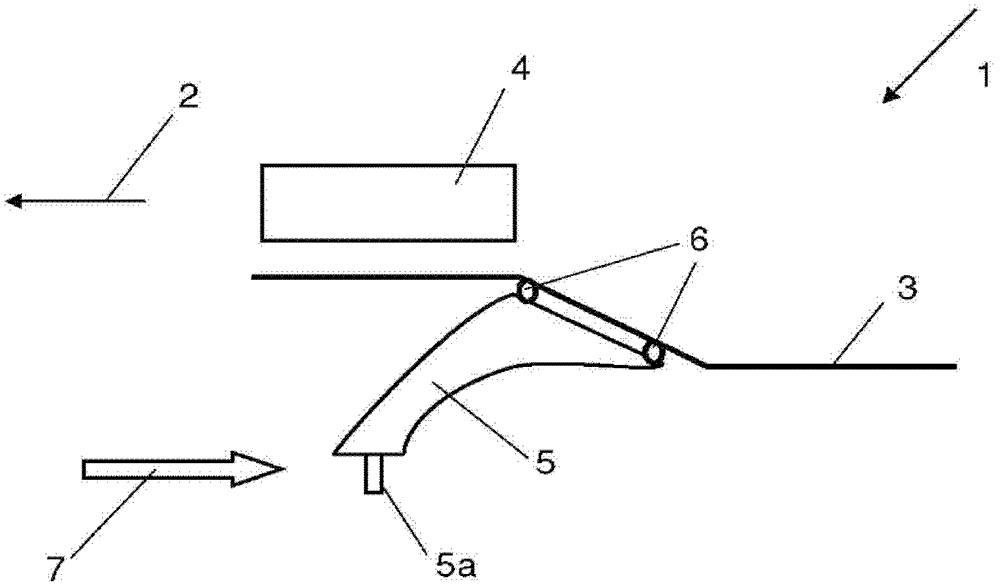
[0017] The sole figure shows a schematic diagram of a part of a motor vehicle. The figures show parts of a vehicle longitudinal part 3 and an engine 4 . The direction of travel of motor vehicle 1 is indicated by arrow 2 . The A-arm 5 and the wheel journal 5 a are connected to the longitudinal part 3 via two assembly points 6 . According to the invention, a force in the direction of the arrow 7 is exerted on the A arm 5 and the associated fastening element is moved into its rearmost position relative to the mounting point 6 .


PUM


Abstract

The method involves fastening and / or assembling a triangle control arm i.e. transverse support (5), using a fastening unit i.e. screw, on an assembling point (6). The associated fastening unit is not completely embedded in a defined assembling end position. Defined force is applied on the triangle control arm, so that the triangle control arm is embedded in a maximum deflection position that is formed due to form closure of the fastening unit. The fastening unit is embedded in an assembling end position, and the defined force is generated by a pneumatic cylinder.

Description

technical field [0001] The invention relates to an assembly method of a lateral control arm. Background technique [0002] In vehicle construction, transverse control arms have long been known. One traditional approach is to use transverse control arms and hybrid spring / shock struts (known as MacPherson struts) as the front wheel suspension system in passenger vehicles. A schematic diagram of such a front wheel suspension system is shown on page 591 of the German version of the "Bosch Motor Handbook" (Kraftfahrtechnisches Taschenbuch, 22nd Edition, 1995). [0003] Typically, the transverse control arm or A-arm of a motor vehicle is fastened or mounted on the body or on the subframe at two points, that is to say in a corresponding manner at the two corners of the triangle. The remaining third corner of this A-arm is usually articulated to the axle body. The axle body is supported by the above-mentioned MacPherson struts in turn, and the support for the MacPherson struts is...

Claims


Application Information

Patent Timeline
Patent Type & Authority Patents(China)
IPC IPC(8): B23P19/00
CPCB60G7/02B60G2204/143
Inventor 胡柏图斯·冯·查普伊
Owner FORD GLOBAL TECH LLC
Features
  • R&D
  • Intellectual Property
  • Life Sciences
  • Materials
  • Tech Scout
  • Unparalleled Data Quality
  • Higher Quality Content
  • 60% Fewer Hallucinations
Learn More