Continuous variable valve lift apparatus

A variable valve lift technology, which is applied in the direction of valve devices, machines/engines, mechanical equipment, etc., can solve the problems of poor engine efficiency, high dynamic load, high manufacturing cost, etc., and achieve friction reduction, dynamic load reduction, The effect of simple configuration

Inactive Publication Date: 2012-05-30
HYUNDAI MOTOR CO LTD +1
View PDF5 Cites 14 Cited by
  • Summary
  • Abstract
  • Description
  • Claims
  • Application Information

AI Technical Summary

Problems solved by technology

[0006] However, the conventional variable valve lift device requires many components and is expensive to manufacture
Also, the friction between each element is quite high, the dynamic load is high, and the efficiency of the engine is not good

Method used


Image

  • Continuous variable valve lift apparatus
  • Continuous variable valve lift apparatus
  • Continuous variable valve lift apparatus

Examples


Embodiment Construction

[0025] Reference will now be made in detail to various embodiments of the invention, examples of which are illustrated in the accompanying drawings and described below. While the invention will be described in conjunction with exemplary embodiments, it will be appreciated that present description is not intended to limit the invention to those exemplary embodiments. On the contrary, the invention is intended to cover not only the exemplary embodiments but also various alternatives, modifications, equivalents and others which may be included within the spirit and scope of the invention as defined by the appended claims. implementation.

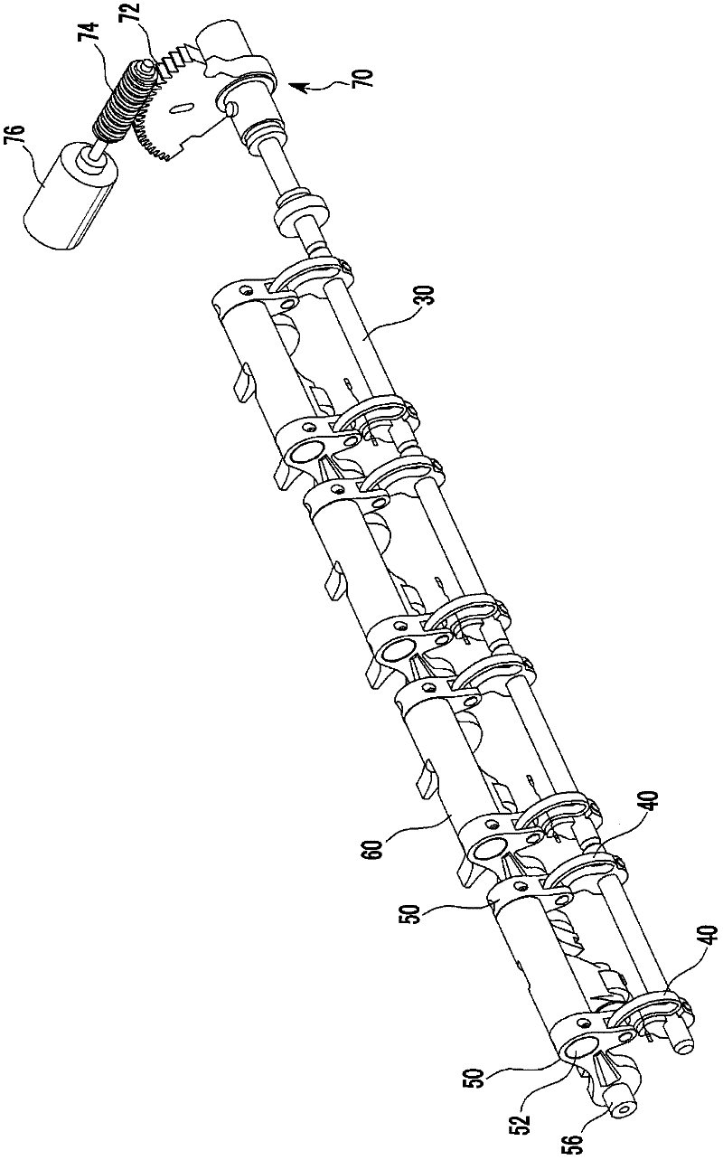
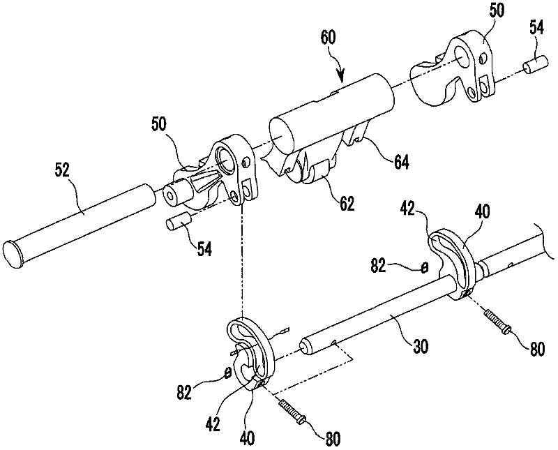
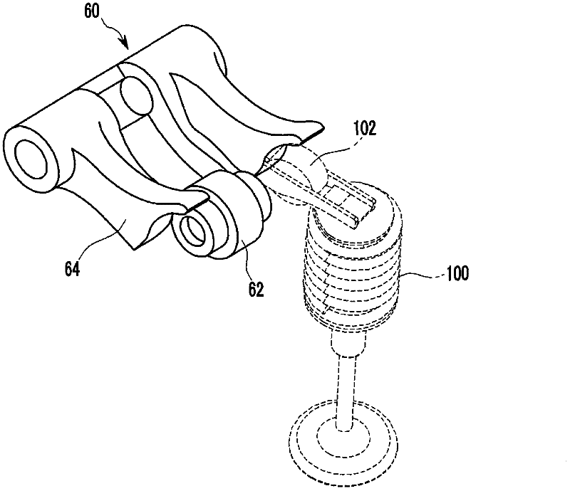
[0026] refer to Figure 1 to Figure 5 As shown, the exemplary continuously variable valve lift device according to the present invention may include: a camshaft 10; a first cam 20 arranged on the camshaft 10; an actuating shaft 30 parallel to the camshaft 10; the actuating link 40 of the moving shaft 30; the swing arm 50 rotatably coupled to ...


PUM


Abstract

A continuous variable valve lift apparatus may include a camshaft, a first cam disposed on the camshaft, an actuating shaft parallel to the cam shaft, an actuating lever connected to the actuating shaft, a swing arm rotatably coupled to the actuating lever and an engine, a second cam pivotally connected to the swing arm and contacting the first cam to open a valve unit and a control portion which is connected to the actuating shaft and selectively rotates the actuating shaft for pivoting center of the swing arm to move.

Description

[0001] Cross References to Related Applications [0002] This application claims priority from Korean Patent Application No. 10-2010-0120915 filed in the Korean Intellectual Property Office on Nov. 30, 2010, the entire contents of which are hereby incorporated by reference for all purposes. technical field [0003] The invention relates to a valve lift device. More particularly, the present invention relates to a continuously variable valve lift device, which can adjust the valve lift. Background technique [0004] An internal combustion engine generates power by burning fuel in a medium of air drawn into a combustion chamber in a combustion chamber. To get air in, the intake valves are operated via the camshaft, and while the intake valves are open, air is drawn into the combustion chamber. In addition, the exhaust valve is operated by the camshaft, and while the exhaust valve is open, the combustion gas is discharged from the combustion chamber. [0005] The optimal ope...

Claims


Application Information

Patent Timeline
Patent Type & Authority Applications(China)
IPC IPC(8): F01L13/00
CPCF01L1/12F01L13/00F01L13/0021F01L2013/0068
Inventor 卢泰勋李宗原
Owner HYUNDAI MOTOR CO LTD
Why Eureka
Try Eureka