End-surface key structure for coupler
A technology of couplings and end-face keys, applied in the direction of couplings, elastic couplings, key connections, etc., can solve problems such as frequent occurrence of couplings, increase firmness, improve stability, and improve transmission torque efficiency effect
- Summary
- Abstract
- Description
- Claims
- Application Information
AI Technical Summary
Problems solved by technology
Method used
Image
Examples
Embodiment 1
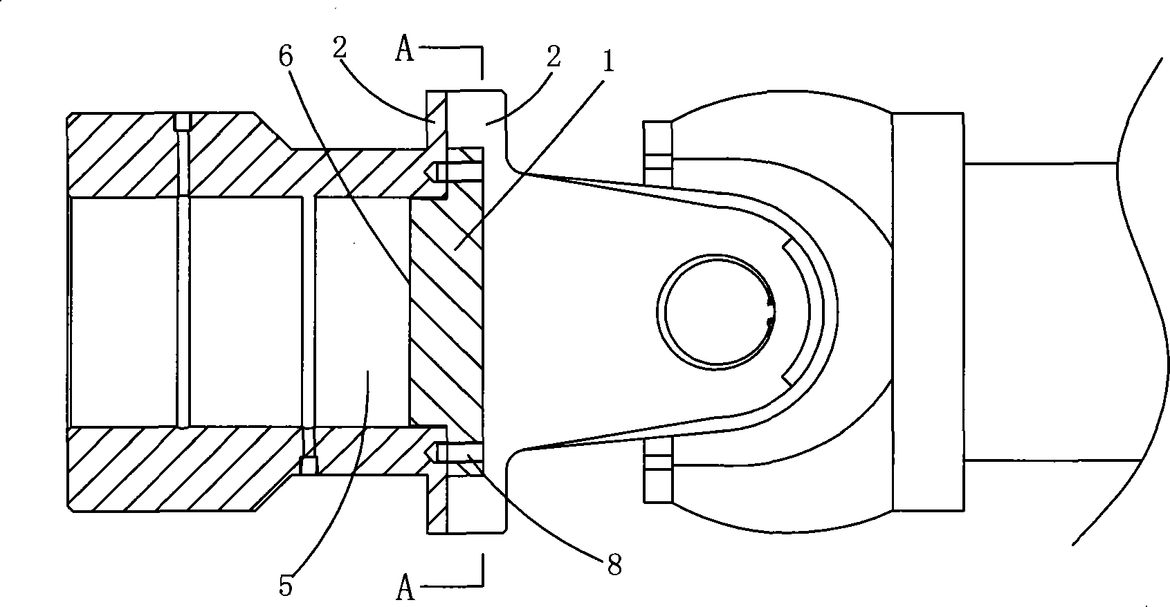
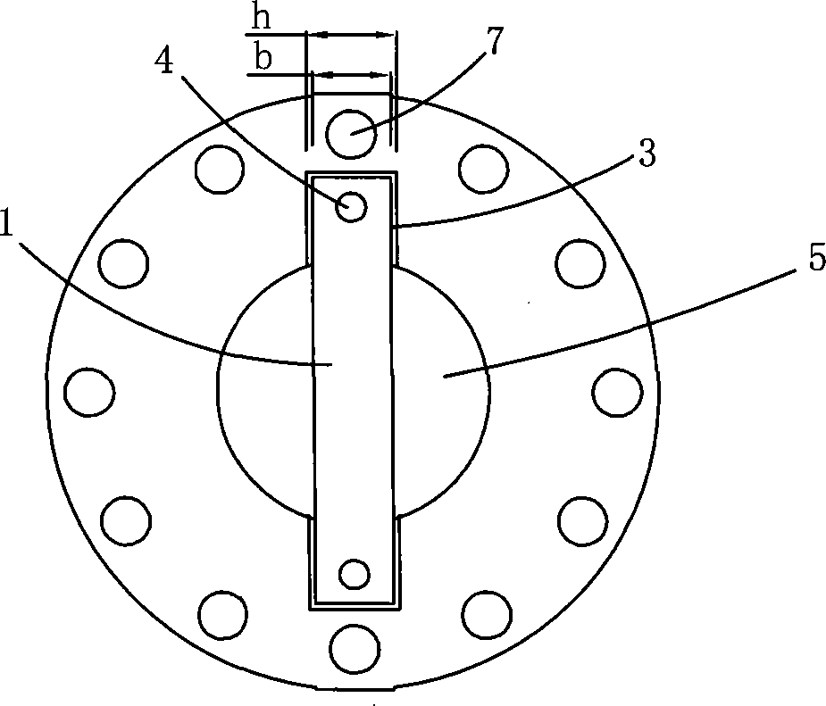
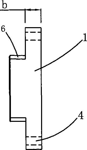
[0028] The end face key structure for the coupling of this embodiment is as follows: figure 1 and figure 2 As shown, it includes the key 1 and the keyway 3 made on the end face of the coupling flange 2. The two ends of the key 1 are formed with through holes 4 for fastening the key 1 and the coupling flange 2. , the fastener of this embodiment adopts the screw 8 commonly used for the end face key of the existing coupling. like figure 1 and image 3 As shown, the side of the key 1 forms a boss 6 that can be embedded in the shaft hole 5 of the coupling flange 2; when the key 1 cooperates with the keyway 3, the boss 6 and the shaft hole 5 form a contact surface that matches each other, that is, the boss The profile of 6 adapts to the shape of shaft coupling flange 2 shaft holes 5 (certainly boss 6 and shaft holes 5 also can form line contact). The keyway 3 is formed by the end face keyway located on the end face of the coupling flange 2 .
[0029] like image 3 As shown, t...
Embodiment 2
[0032] The end face key structure for the coupling of this embodiment is as follows: Figure 5 and Figure 6 As shown, it is changed on the basis of Embodiment 1, except that it is the same as Embodiment 1. The differences are: 1) The keyway 3 traverses the end face of the coupling flange 2; 2) The through hole 4 and the coupling method Align the bolt hole 7 on the end face of the flange 2; 3) Remove the screw 8, and fasten the key 1 and the coupling flange 2 with the bolt 9 through the through hole 4 and the bolt hole 7; 4) The contact surface of the key 1 and the keyway 3 It is a transition fit, that is, the thickness b of the key 1 is basically equal to the width h of the key groove 3; 5) The contact surface between the boss 6 and the shaft hole 5 is a transition fit.
Embodiment 3
[0034] The end face key structure for the coupling of this embodiment is as follows: Figure 7 and Figure 8 As shown, it is changed on the basis of the second embodiment, except that it is the same as the second embodiment. The difference is that the boss 6 is formed on the two sides of the key 1, one of which is a single-step boss, and the other The sides are double stepped bosses.
[0035] Obviously, the shape of the boss 6 can be any shape suitable for the shape of the shaft hole 5 of the coupling flange 2 .
PUM
 Abstract
Description
Claims
Application Information
 - R&D
- Intellectual Property
- Life Sciences
- Materials
- Tech Scout
- Unparalleled Data Quality
- Higher Quality Content
- 60% Fewer Hallucinations
Browse by: Latest US Patents, China's latest patents, Technical Efficacy Thesaurus, Application Domain, Technology Topic, Popular Technical Reports.
© 2025 PatSnap. All rights reserved.Legal|Privacy policy|Modern Slavery Act Transparency Statement|Sitemap|About US| Contact US: help@patsnap.com


