Display apparatus

A technology for displaying equipment and image data, applied in static indicators, instruments, etc., can solve the problems of reduced display quality and image quality degradation, and achieve the effect of preventing false color and excellent display quality

Inactive Publication Date: 2012-05-30
CANON KK
View PDF8 Cites 19 Cited by
  • Summary
  • Abstract
  • Description
  • Claims
  • Application Information

AI Technical Summary

Problems solved by technology

When the light-emitting regions 34r, 45g, and 36b in the long triangular arrangement 54 emit light, they cause image quality degradation such as false colors, color moiré, and roughness at the edge of the image, resulting in a significant decrease in display quality

Method used


Image

  • Display apparatus
  • Display apparatus
  • Display apparatus

Examples


Embodiment Construction

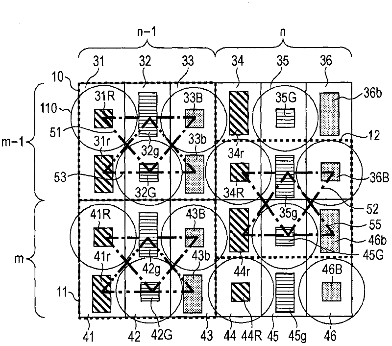
[0048] figure 1 The configuration of pixels in a display device according to an embodiment of the present invention is shown.

[0049] figure 1 The arrangement of the light-emitting area in the Figure 14 in the same. RGB organic electroluminescent (EL) elements are periodically arranged in the row direction, and are connected to the pixel circuits 31 to 36 and 41 to 46 . Organic EL elements of the same color are connected to pixel circuits in the same subcolumn. and Figure 14 Similarly, three RGB sub-columns form a column.

[0050] The pixel circuit 31 is connected to two light emitting regions 31r and 31R. An organic EL element ELA having a flat surface not including a lens is arranged in the light emitting region 31 r (and every other light emitting region indicated by a reference numeral having a lowercase suffix). The organic EL element ELB having a lens on the surface is arranged on the light emitting region 31R (and every other light emitting region indicated ...


PUM


Abstract

Provided is a display apparatus comprising light-emitting elements having colors cyclically aligned, pixel circuits and a processing circuit, the light-emitting elements each having two light-emitting regions aligned in the column direction so as to invert the positions of the two light-emitting regions in accordance with a cycle of the colors, and the two light-emitting regions having different optical characteristics and emitting light alternately over two consecutive frame periods so that the light-emitting regions which emit light in each frame period have the same optical characteristics.

Description

technical field [0001] The present invention relates to display devices, and in particular to display devices comprising organic electroluminescent elements. Background technique [0002] Organic electroluminescence (EL) elements emit light when an electric current is applied to a thin organic layer between two electrodes. Such organic EL elements are two-dimensionally arranged to constitute a display device. [0003] There is a problem that the light extraction efficiency of the organic EL element is low. Although light is emitted at various angles from the thin light-emitting layer, total reflection occurs at the boundary surface between a layer sandwiching the light-emitting layer (such as a protective layer) and an external space, so that light is confined within the light-emitting element and most of the light is blocked. Light is extracted into the outer space. In order to solve this problem, various solutions have been proposed. [0004] Japanese Patent Laid-Open ...

Claims


Application Information

Patent Timeline
Patent Type & Authority Applications(China)
IPC IPC(8): G09G3/32
CPCG09G2300/0452G09G3/3275G09G3/3233
Inventor 川野藤雄坂口清文
Owner CANON KK
Why Eureka
Try Eureka