Combined electronic mutual inductor

An electronic transformer and combined technology, applied in the direction of inductors, circuits, transformers, etc., can solve the problems that the internal electric field distribution is difficult to obtain uniform, it is difficult to meet the high performance test, and the shielding effect has poor anti-interference ability. Uniform distribution, reducing tip discharge, good insulation performance

Inactive Publication Date: 2012-05-30
JIANGSU SIYUAN HERTZ TRANSFORMER
View PDF8 Cites 5 Cited by
  • Summary
  • Abstract
  • Description
  • Claims
  • Application Information

AI Technical Summary

Problems solved by technology

my country's patent "New high-voltage combined independent electronic current and voltage transformer" patent number: 2007200300527.1, discloses an electronic current and voltage transformer. Although this structure significantly reduces the overall weight, due to structural reasons, the overall It is difficult to obtain a uniform distribution of the internal electric field, and its shielding effect and anti-interference ability are poor, and it is difficult to meet the requirements of high-performance testing. Therefore, it is necessary to improve the existing combined electronic current and voltage transformers to improve equipment. The effect of using

Method used


Image

  • Combined electronic mutual inductor
  • Combined electronic mutual inductor
  • Combined electronic mutual inductor

Examples


Embodiment Construction

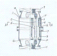
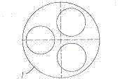
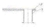
[0019] Refer to attached figure 1 , attached figure 2 , attached image 3 , attached Figure 4 , attached Figure 5 , attached Image 6 , a combined electronic transformer of the present invention consists of a housing 1, a primary conductive rod 2, a current coil shielding cylinder 3, a current coil 4, an upper positioning flange 5, a shielding cylinder 6, an intermediate electrode 7, a grounding electrode 8, The upper pot insulator 9, the lower positioning flange 10, the lower pot insulator 11, and the insulating support 12 are composed of an upper positioning flange 5 fixed on the upper half of the shell 1a of the shell 1; the shell 1 It is a metal cylinder made of aluminum alloy with a low expansion coefficient. The outer surface of the upper half of the shell 1a of the shell 1 has an arc-shaped structure, and the outer surface of the lower half of the shell 1b of the shell 1 has an arc-shaped structure; The upper basin insulator 9 is connected to the shell 1; the pr...


PUM


Abstract

The invention relates to a combined electronic mutual inductor. The combined mutual inductor comprises a shell, primary conductive rods, current coil shielding cylinders, current coils, shielding cylinders, intermediate electrodes, grounding electrodes, an upper pan-type insulator and a lower pan-type insulator, wherein the upper half shell of the shell is fixedly provided with upper positioning flanges; the primary conductive rods are connected with a conductive body of the upper pan-type insulator; the upper positioning flanges are fixedly provided with the current coil shielding cylinders; the current coils are arranged at the periphery of the current coil shielding cylinders; the shielding cylinders are arranged at the periphery of the primary conductive rods; and one end of each shielding cylinder is connected with the primary conductive rods, and the other end of the shielding cylinder is separated from the primary conductive rods. A current mutual inductor and a voltage mutual inductor are combined into a whole, so that the whole combined electronic mutual inductor has a compact structure and a small volume. The shielding cylinders, the intermediate electrodes, the grounding electrodes and the shell are made of aluminum alloy materials with low expansion coefficients, air vents are formed on the shielding cylinders, and all ports are designed into arc-shaped forms, so that point discharge is reduced, and internal electric fields are uniform.

Description

technical field [0001] The invention relates to an electronic transformer used in the electric power industry, in particular to a combined electronic transformer. Background technique [0002] After retrieving relevant patent documents, no combined electronic transformer with the same structure as the present invention has been retrieved. Existing high-voltage transformers are mainly divided into voltage transformers and current transformers. High-voltage current transformers are further divided into oil-immersed current transformers and sulfur hexafluoride current transformers. Due to structural reasons, oil-immersed current transformers and sulfur hexafluoride current transformers generally have iron cores, and electromagnetic induction is used to convert data. This type of current transformers uses iron cores, so magnetic saturation occurs. The electromagnetic induction ability is obviously reduced, and the volume is large, so that the overall weight is obviously heavie...

Claims


Application Information

Patent Timeline
Patent Type & Authority Applications(China)
IPC IPC(8): H01F38/34H01F27/36G01R15/18
Inventor 王占宾杨建冒爱丽王长祥徐明利付加强
Owner JIANGSU SIYUAN HERTZ TRANSFORMER
Why Eureka
Try Eureka