Testing method and equipment for intelligent antenna broadcast forming of base station

A smart antenna and broadcast shaping technology, applied in transmission monitoring, electrical components, transmission systems, etc., can solve the problems of limited space in microwave anechoic chambers, avoid external interference signals and environmental reflection and refraction signals, and have accurate corresponding relationships. The effect of high measurement accuracy

Active Publication Date: 2014-05-28
DATANG MOBILE COMM EQUIP CO LTD
View PDF6 Cites 4 Cited by
  • Summary
  • Abstract
  • Description
  • Claims
  • Application Information

AI Technical Summary

Problems solved by technology

[0006] The disadvantage of the existing measurement method 1) is that it will be affected by the external environment, such as reflected signals and interference signals from surrounding objects
[0007] The disadvantage of the existing measurement method 2) is: the space of the microwave anechoic chamber is limited, and it is impossible to construct a very long space distance

Method used


Image

  • Testing method and equipment for intelligent antenna broadcast forming of base station
  • Testing method and equipment for intelligent antenna broadcast forming of base station
  • Testing method and equipment for intelligent antenna broadcast forming of base station

Examples


Embodiment Construction

[0060] Specific embodiments of the present invention will be described below in conjunction with the accompanying drawings.

[0061] Firstly, the schematic diagram for calculating the phase difference value is introduced.

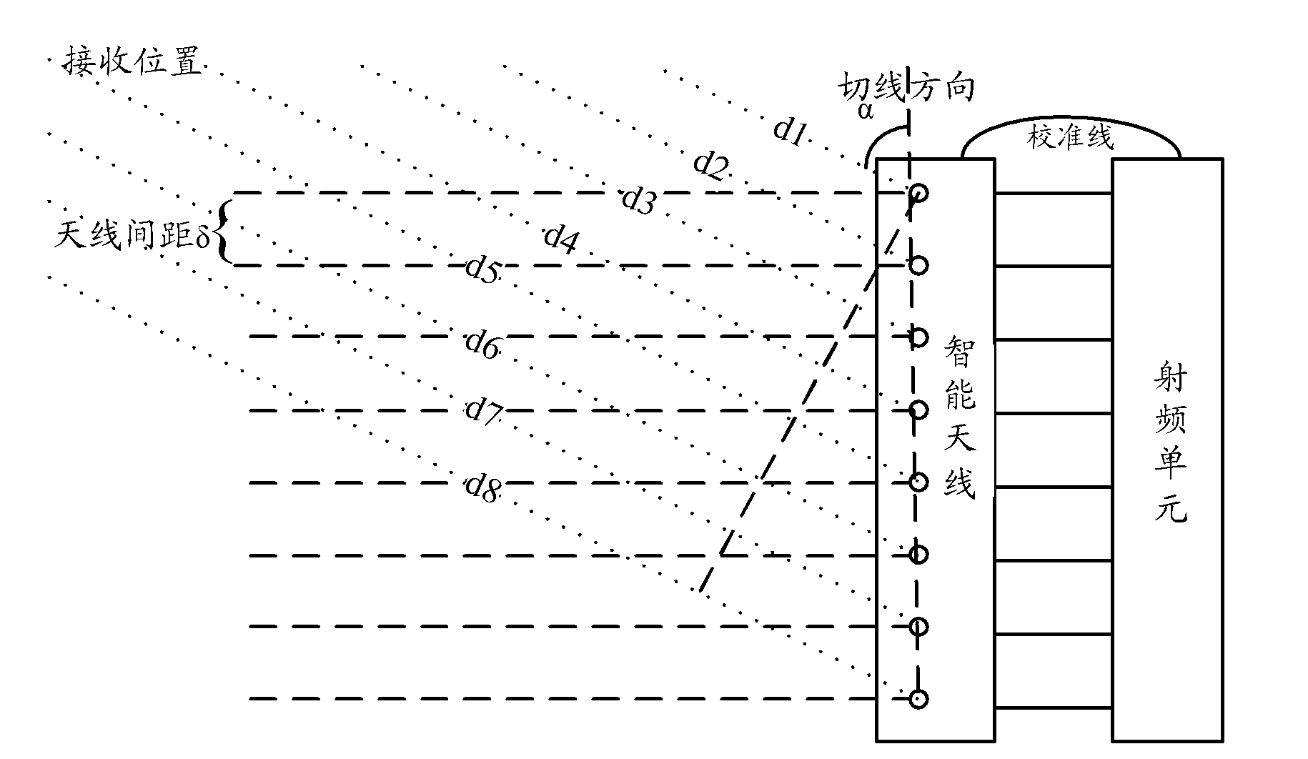
[0062] figure 1 Calculate the schematic diagram for the phase difference value, in the relationship shown in the figure, there are:

[0063] When the distance between the receiving position and the antenna is relatively long, it can be approximately considered that the connecting line between the receiving position and each antenna element is a parallel line, and the distance from the receiving position to each antenna in the figure is d1~d8.

[0064] Calculate the phase difference between the array elements: the wavelength of the known signal is λ, the angle between the receiving position and the antenna tangent is α, and the distance between the antennas is δ. The phase difference between the antennas can be calculated by the following formula:

[0065]...


PUM


Abstract

The invention discloses a testing method and equipment for intelligent antenna broadcast forming of a base station. The method includes firstly, compensating phase differences of each way between an output end of a power divider and an antenna output end of an intelligent antenna coupling disc to be uniform by adjusting numerical control phase shifters; secondly, correcting a phase between a radio-frequency unit and the intelligent antenna coupling disc to uniform phase differences of each channel; thirdly, determining calculation phase differences from receiving positions at all angles to be tested to each antenna within a base station antenna coverage; fourthly, compensating the calculation phase differences of all angles to phases of the numerical control phase shifters to acquire broadcast power of a frequency spectrograph at the angle when the base station transmits broadcast signals; and fifthly, using the power determined according to the angle and the broadcast power at the angle as a broadcast forming result. The testing method and the equipment for intelligent antenna broadcast forming of the base station is capable of avoiding external interfering signals and environmentally reflected and refracted signals, high in testing precision and accurate in corresponding relation among different testing positions and signal powers.

Description

technical field [0001] The invention relates to communication equipment, in particular to a test method and equipment for base station smart antenna broadcast shaping. Background technique [0002] In the TD-SCDMA (Time Division Synchronized Code Division Multiple Access, Time Division Synchronized Code Division Multiple Access) base station smart antenna forming test, the existing solution is to use a real antenna to transmit radio frequency signals. There are two methods for measurement: [0003] 1) Use drive test terminals to collect broadcast signals outdoors; [0004] 2) Measure the signal strength with a field strength meter in a microwave darkroom. [0005] The essence of the existing test method is that the signals emitted by multiple antennas are superimposed in space, and the signal strength is measured by changing the position of the receiving end in space. [0006] The disadvantage of the existing measurement method 1) is that it will be affected by the externa...

Claims


Application Information

Patent Timeline
Patent Type & Authority Patents(China)
IPC IPC(8): H04B17/00H04B1/12H04B17/12
Inventor 钟山虎
Owner DATANG MOBILE COMM EQUIP CO LTD
Why Eureka
Try Eureka