

Copper foil composite
A composite, copper foil technology, used in the manufacture of printed circuit precursors, electronic equipment, printed circuits, etc., can solve problems such as poor electromagnetic wave shielding, and achieve the effect of improving processability
- Summary
- Abstract
- Description
- Claims
- Application Information
AI Technical Summary
Problems solved by technology
Method used
Image

Examples
Embodiment
[0048] 1. Electromagnetic wave shielding material
[0049]
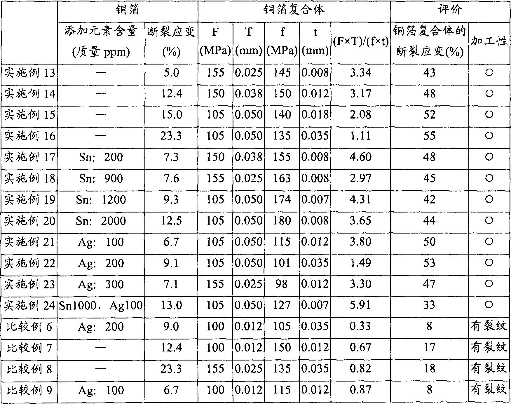
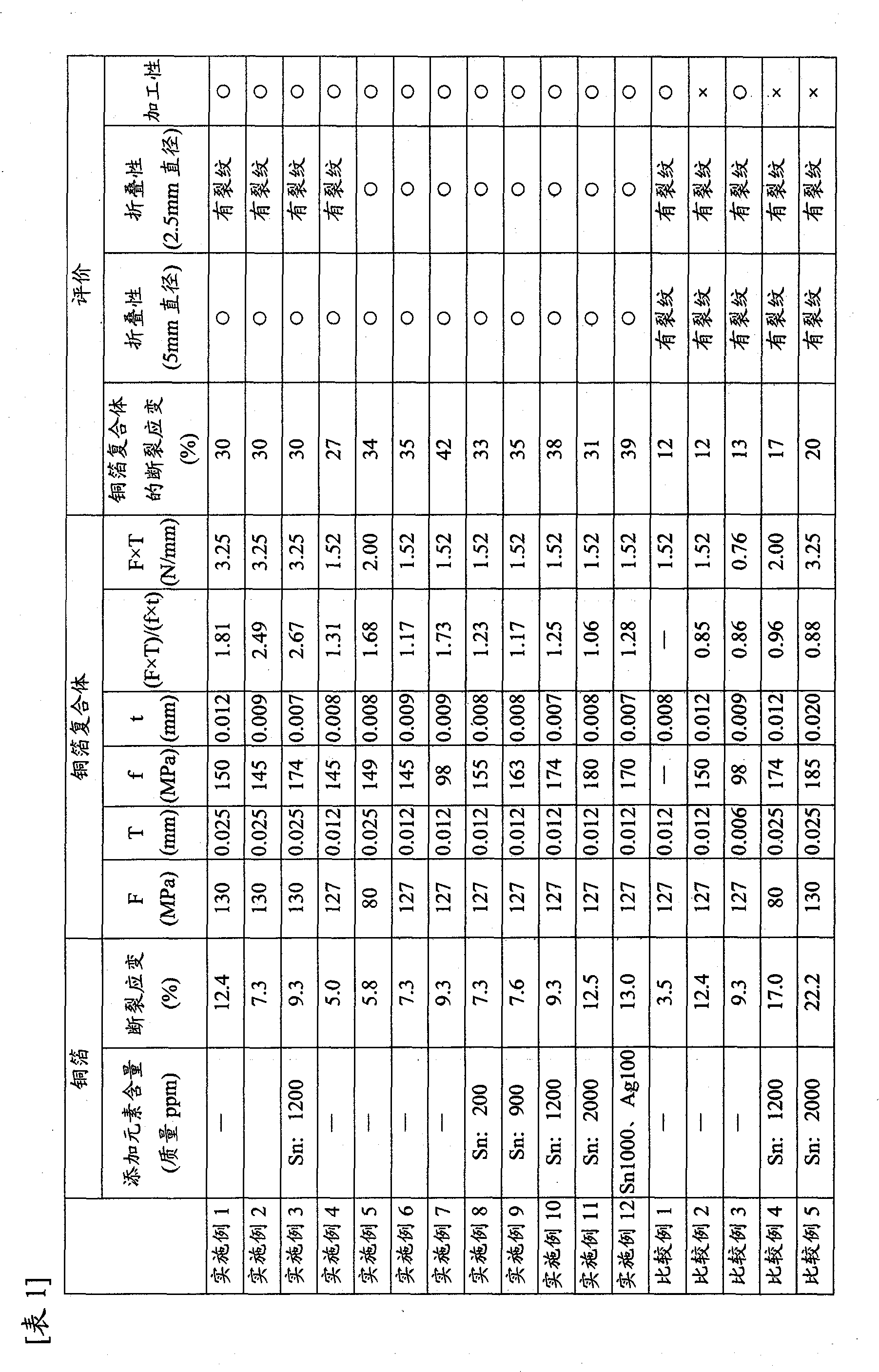
[0050] Tough copper ingots are hot-rolled, and after surface cutting to remove oxides, cold-rolling, annealing and pickling are repeated to make it thinner to a specified thickness, and finally annealing is performed to obtain workability-guaranteed copper foil. The tension during cold rolling and the rolling conditions (reduction conditions) in the width direction of the rolled material are kept uniform so that the copper foil has a uniform structure in the width direction. In the subsequent annealing, the temperature was controlled using a plurality of heaters, and the temperature of copper was measured and controlled so as to form a uniform temperature distribution in the width direction. Copper foil is produced by adding a predetermined amount of Sn or Ag to several copper ingots.
[0051] A commercially available biaxially stretched PET film of a predetermined thickness was bonded to the above-mentioned copp...
PUM
 Abstract
Description
Claims
Application Information