
Signal delay time measurement method

A technology of signal delay and measurement method, which is applied in the field of measurement, can solve the problems of taking too much time and not being able to distinguish the signal delay time from it, and achieve the effect of short measurement time

Inactive Publication Date: 2013-11-06
CHROMA ATE
View PDF3 Cites 0 Cited by
  • Summary
  • Abstract
  • Description
  • Claims
  • Application Information

AI Technical Summary

Problems solved by technology

[0004] In the prior art, if a signal frequency with a resolution greater than the sampling frequency is required, it is necessary to continuously measure the signal of multiple cycles, then accumulate the time of multiple cycles, and calculate the average value, but such a frequency measurement method needs to spend More time, and the calculated frequency is the average frequency of many periodic waves, from which the observer cannot distinguish the signal delay time of each periodic wave

Method used


Image

  • Signal delay time measurement method
  • Signal delay time measurement method
  • Signal delay time measurement method

Examples


Embodiment Construction

[0028] Below in conjunction with accompanying drawing, structural principle and working principle of the present invention are specifically described:

[0029] The invention relates to a measuring method, in particular to a measuring method of signal delay time. A preferred embodiment is listed below to illustrate the present invention, but those skilled in the art know that this is only an example, not intended to limit the invention itself. The content of this preferred embodiment is described in detail as follows.

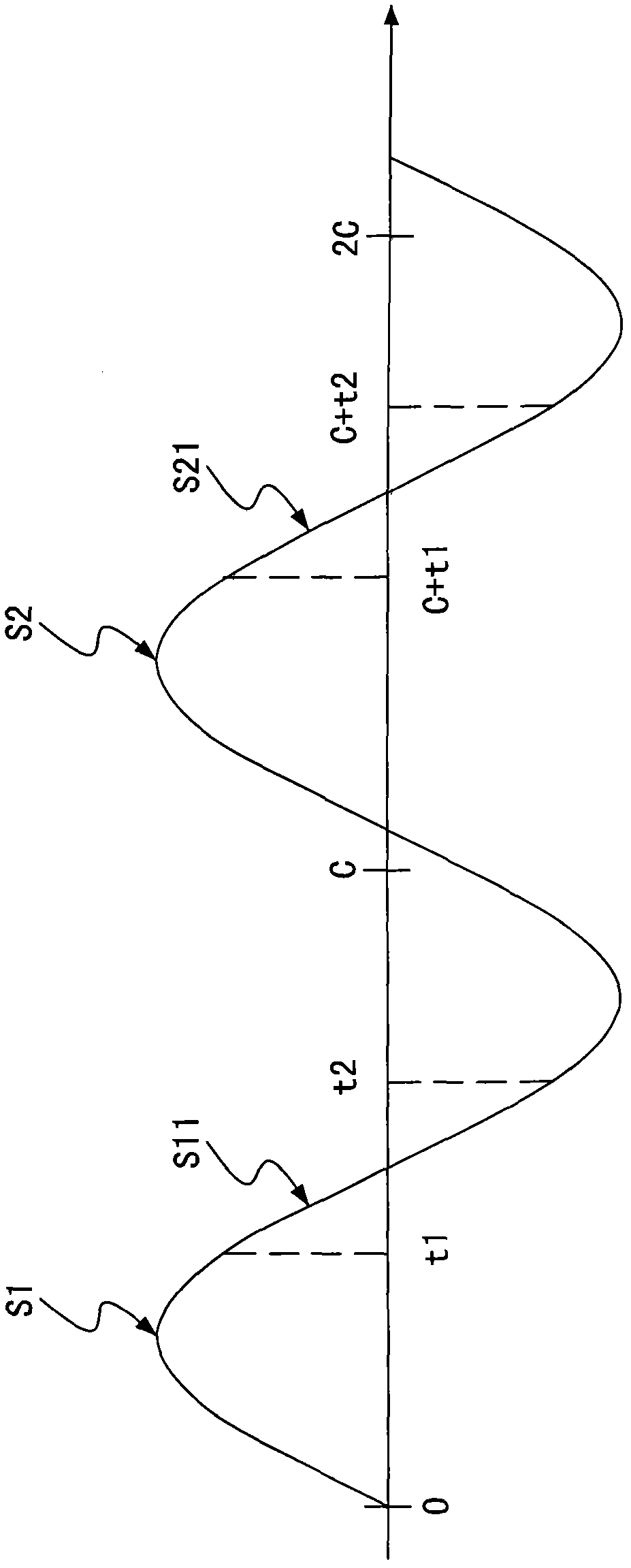
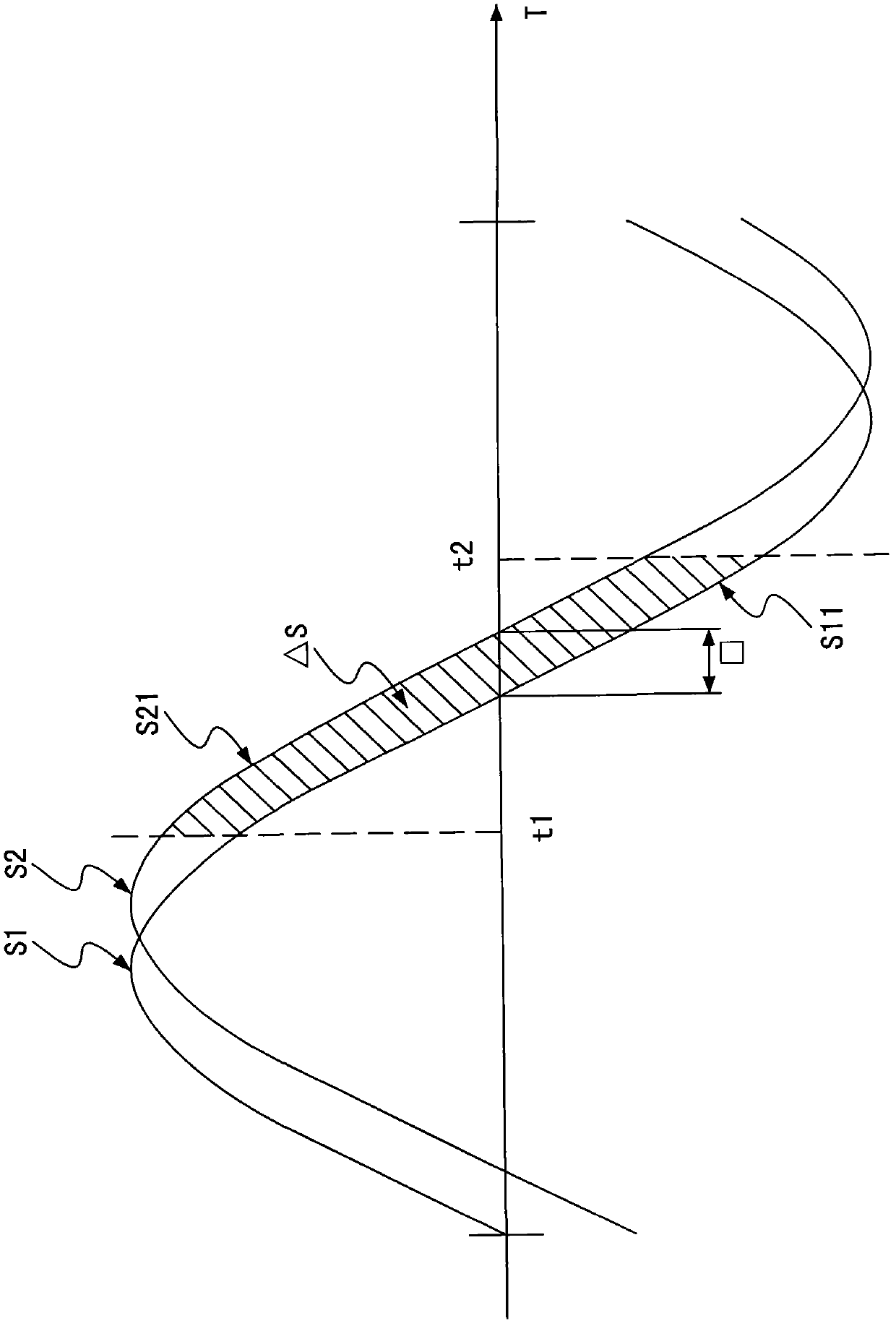
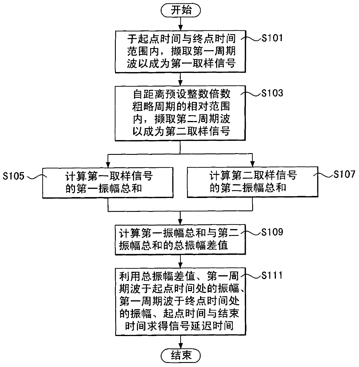
[0030] see figure 1 , figure 2 and image 3 , figure 1 is a schematic diagram of the signal to be tested, figure 2 is a schematic diagram of the superimposition of the first periodic wave and the second periodic wave, image 3 It is a flow chart of the method for measuring the signal delay time of the present invention. The method for measuring the signal delay time of the present invention is used to measure a signal to be measured with a rough cycle...


PUM


Abstract

The invention discloses a signal delay time measurement method used for measuring the signal delay time between a first period wave and a second period wave. By using the measurement method, the first period wave can be used as a first sampling signal in a range of a starting time and an ending time, and the second period wave can be used as a second sampling time in a preset integer multiple of a rough period range between the starting time and the ending time. The sum of the first amplitudes of the first sampling signal can be calculated, and the sum of the second amplitudes of the second sampling signal also can be calculated. By using the amplitudes difference between the first amplitudes and the second amplitudes, the amplitude of the first period wave at the starting time, the amplitude of the second period wave at the ending time, the starting time and the ending time, the signal delay time can be calculated.

Description

technical field [0001] The invention relates to a measuring method, in particular to a measuring method of signal delay time. Background technique [0002] The accuracy of frequency measurement, in addition to its own specifications, will also affect the accuracy of other measurement values, because many measurement values ​​are calculated based on the signal period, such as effective value (root mean square; rms), Harmonic components and total harmonic distortion (Total Harmonic Distortion; THD), so accurate frequency measurement is quite necessary. [0003] However, the direct detection of the signal frequency on the hardware is very susceptible to subtle noise and the resolution of the sampling clock (sampling clock), so that the accuracy of the measured frequency is limited. [0004] In the prior art, if a signal frequency with a resolution greater than the sampling frequency is required, it is necessary to continuously measure the signal of multiple cycles, then accumu...

Claims


Application Information

Patent Timeline
Patent Type & Authority Patents(China)
IPC IPC(8): G01R23/06
Inventor 张志交
Owner CHROMA ATE
Learn More