Target model-based device monitoring system

A device monitoring and object model technology, applied in the direction of comprehensive factory control, comprehensive factory control, electrical program control, etc., can solve the problems of flat namespace, unpredictable application system, inability to connect into a built-in relationship and interdependence, etc. , to achieve the effect of high cohesion

Active Publication Date: 2012-06-06
SHANGHAI BAOSIGHT SOFTWARE CO LTD
View PDF4 Cites 11 Cited by
  • Summary
  • Abstract
  • Description
  • Claims
  • Application Information

AI Technical Summary

Problems solved by technology

Although the method purely based on label points is simple and easy to switch and transplant between different projects, it still has shortcomings: the namespace is too flat, and the inheritance relationship between elements is lacking, and they cannot be connected into intelligent objects with built-in re

Method used


Image

  • Target model-based device monitoring system
  • Target model-based device monitoring system
  • Target model-based device monitoring system

Examples


Embodiment 1

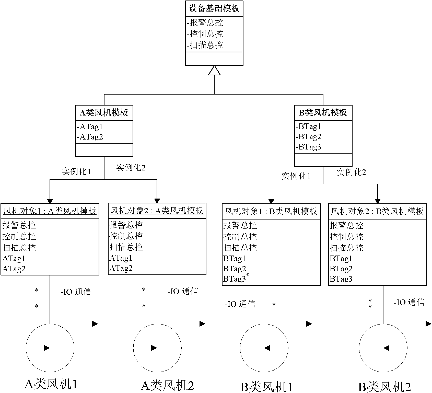
[0029] Embodiment one, such as figure 2 As shown, model the fan, instantiate multiple objects, and associate the objects with the actual equipment.

[0030] 1. Various logical master control switches are used as general attributes of the equipment basic class template;

[0031]2. According to the type of fan equipment, two types of fan templates are derived, and various physical I / O interfaces of related equipment types are used as the own attributes of the class template;

[0032] 3. There are four devices in total, A-type fans 1 and 2, and B-type fans 1 and 2. The two types of templates are instantiated respectively to obtain two objects, corresponding to A and B, a total of four fan devices;

[0033] 4. Finally, configure the I / O address on the corresponding physical device for the own attribute tag point of each object.

Embodiment 2

[0034] In the second embodiment, the power of the pump is calculated using calculation points.

[0035] 1. Configure the self-owned attributes tagI and tagU in the class template of the pump equipment, which respectively represent the input current intensity and voltage of the equipment;

[0036] 2. Configure the calculation point tagP, whose calculation formula is tagP=tagI*tagU;

[0037] 3. Instantiate the pump template and associate the object with the actual device, and collect the input current intensity and voltage value of the pump device in real time through the drive;

[0038] 4. Observe the input power of the equipment in real time through the calculation point tagP.

Embodiment 3

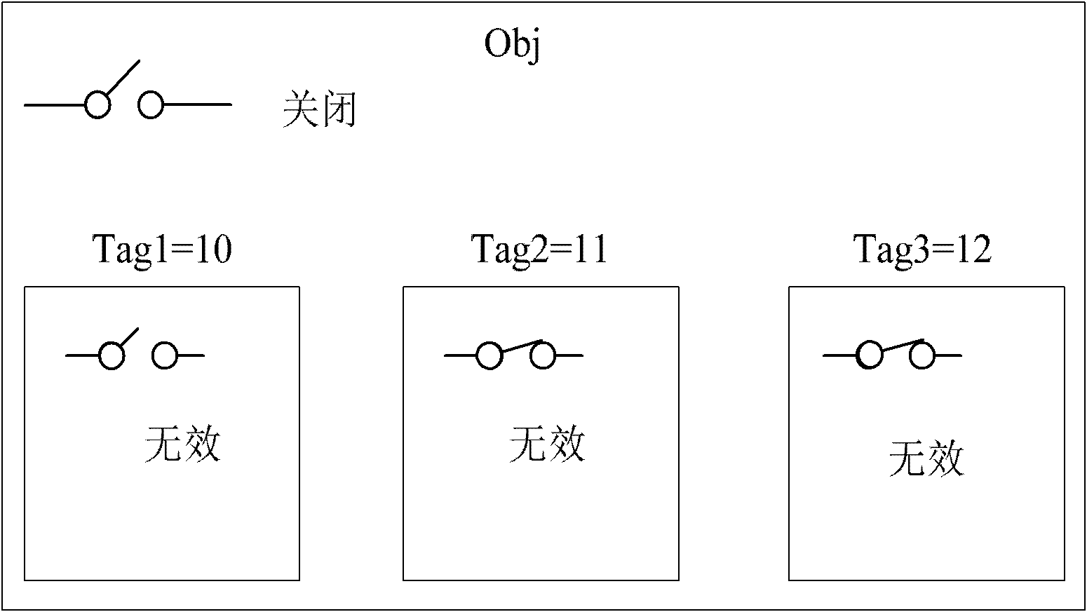
[0039] Embodiment 3, equipment data quality statistics.

[0040] 1. Add 100 own attributes in the class template of the fan equipment, named tag1, tag2, ..., tag100;

[0041] 2. Instantiate the claimed object FunObj, which is the subordinate variables tag1, tag3, tag5, ... of FunObj are respectively associated with valid device I / O addresses, and tag2, tag4, tag6, ... are associated with invalid addresses;

[0042] 3. Run the monitoring system and collect data from the fan equipment in real time;

[0043] 4. Observe the data quality statistics of FunObj. If everything is normal, the statistics should be 50, indicating that 50 tag points cannot collect data normally.


PUM


Abstract

The invention relates to a target model-based device monitoring system, which comprises an abstract and instantiation module of a class template, a target calculation point managing module, a target attribute statistics module and a target logic main control module, wherein the abstract and instantiation module is responsible for deriving different class templates of a device with different types according to a basic class template of the device and for instantiating the class template to a target; the target calculation point managing module is used for adding a calculation point attribute to the class template according to a preset calculation formula; the target attribute statistics module is used for classifying and statistically counting quantities of inferior tag points when the target which is instantiated from the class template stays at different statuses, and the possible status of the inferior tag point includes an alarming status for whether issuing an alarm or not and a data quality status for whether normally collecting the data; and the target logic main control module is used for passing a main control marker bit of the target after the class template is instantiated.

Description

technical field [0001] The invention belongs to the technical field of equipment intelligent monitoring, in particular to an object model-based equipment monitoring system. Background technique [0002] Looking at all kinds of HMI (Human Machine Interfaces, human-machine interface) and SCADA (Supervisory Control And Data Acquisition, data acquisition and monitoring control system) products in the field of equipment monitoring, their main functions basically include data acquisition, equipment control, alarm services and data analysis. Among them, equipment data acquisition means that the system obtains the quantified value of relevant attributes from the physical equipment through the driver program; equipment control means that the system sets the relevant attributes of the physical equipment through the driver program; Pre-set thresholds determine whether to generate an alarm, and maintain historical alarms; data analysis is to analyze the historical trend and trend of da...

Claims


Application Information

Patent Timeline
IPC IPC(8): G05B19/418
CPCY02P90/02
Inventor 赵彬陈志权朱从锋杨波
Owner SHANGHAI BAOSIGHT SOFTWARE CO LTD
Why Eureka
Try Eureka