Double-sided driving system with additional torque compensation function and double-sided driving method of double-sided driving system
A bilateral drive and additional torque technology, applied in the direction of speed adjustment of multiple motors, can solve the problems of long research and development cycle, large volume of two-dimensional motors, high cost, etc., and achieve the goals of improving efficiency, small crosstalk, and reducing product size Effect
- Summary
- Abstract
- Description
- Claims
- Application Information
AI Technical Summary
Problems solved by technology
Method used
Image

Examples
Embodiment 1
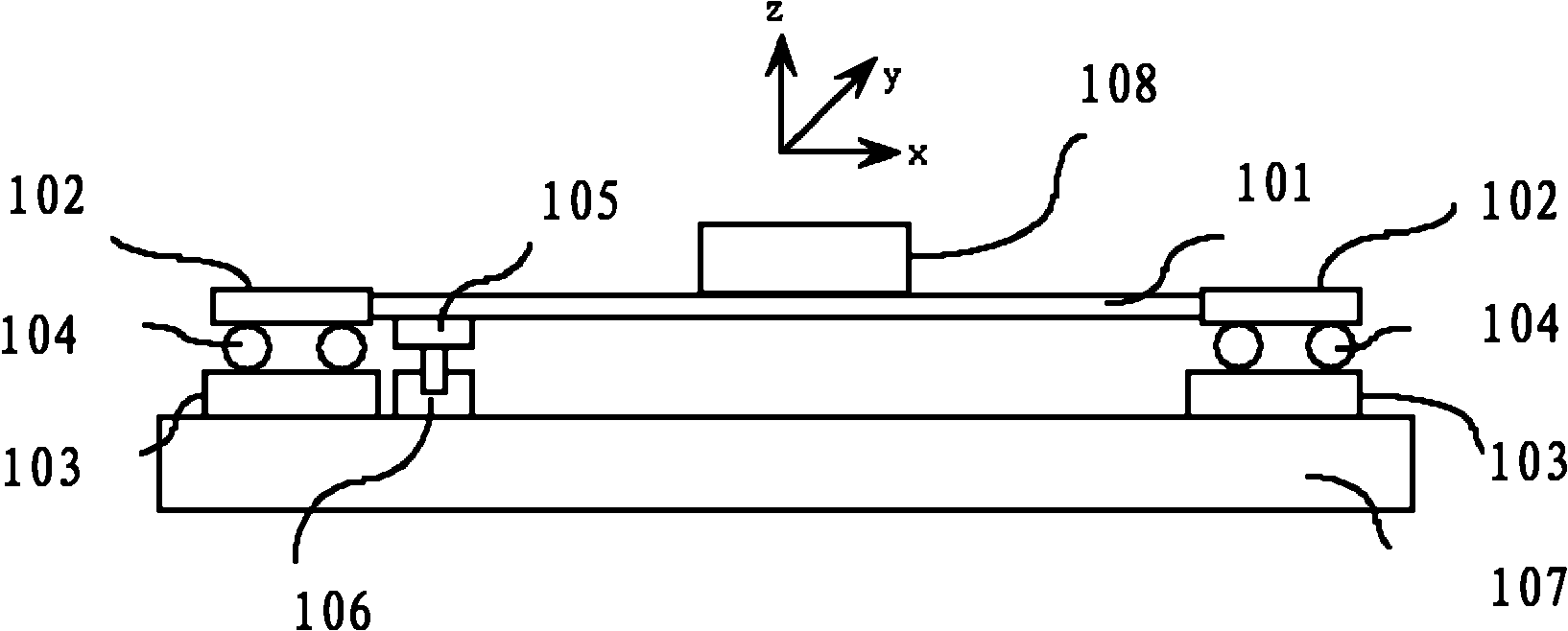
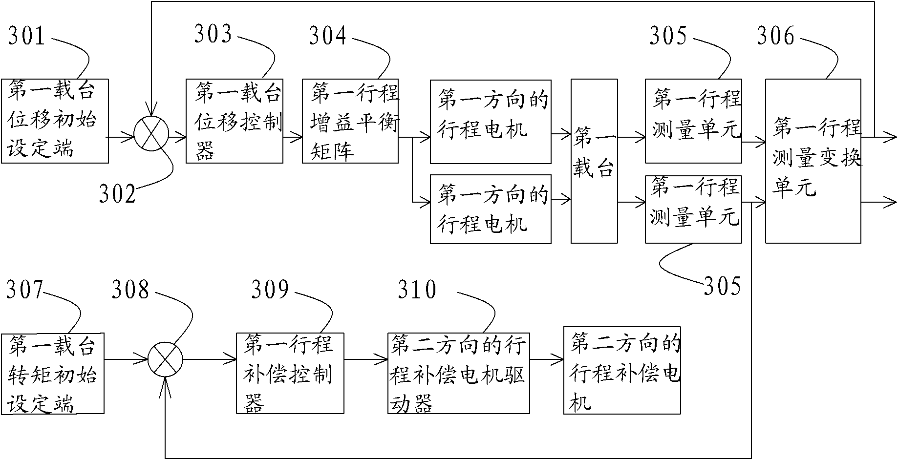
[0034] see figure 1 , figure 1Shown is a schematic structural diagram of a bilateral drive system with an additional torque compensation function according to Embodiment 1 of the present invention. This bilateral drive system with an additional torque compensation function includes: a base 107, a first carrier 101, and a double-sided motor controlled by the first carrier displacement closed-loop control unit arranged between the base 107 and the first carrier 101. Two stroke motors in the first direction that drive the first carrier 101 to move along the Y direction (the stroke motors in the first direction include the stator 103 of the stroke motor in the first direction, the mover 102 and the mover 102 of the stroke motor in the first direction The first air bearing structure 104), two first stroke measuring units 305 (please refer to image 3 ) and a first stroke measurement conversion unit 306 (please refer to image 3 ). The stators 103 of the stroke motors in the two...
Embodiment 2
[0048] see Figure 5 , Figure 5 Shown is a schematic diagram of the structure of a bilateral drive system with an additional torque compensation function according to Embodiment 2 of the present invention. The difference between this embodiment and Embodiment 1 is that: the bilateral drive system also includes a second stage 201 and a travel motor for unilaterally driving the second stage 201 to move along the X direction in the second direction, the The stator 203 of the stroke motor in the second direction is rigidly coupled with the first stage 101, the mover 202 of the stroke motor in the second direction is rigidly connected with the second stage 201, and the stroke in the second direction The stator 203 of the motor is connected with the mover 202 of the stroke motor in the second direction through the third air bearing structure 204 . Since the second stage 201 is driven unilaterally, there is no problem of torque generation in itself. Therefore, it is not necessary ...
Embodiment 3
[0053] see Figure 6 and Figure 7 , Figure 6 Shown is a schematic diagram of the structure of a bilateral drive system with an additional torque compensation function according to Embodiment 3 of the present invention. Figure 7 Shown is the control principle diagram of the second carrier 201 in embodiment 3, the control principle diagram of the first carrier 101 in embodiment 3 is the same as embodiment 1, as image 3shown. The difference between this embodiment and embodiment 1 is:
[0054] The bilateral drive system also includes: a second carrier 201, which is arranged between the first carrier 101 and the second carrier 201 and is used to drive the second carrier 201 bilaterally to move along the X direction in two second directions. (the stroke motor in the second direction includes the stator 203 of the stroke motor in the second direction, the mover 202 and the third air bearing structure in the second direction), two second stroke measuring units 405 and The se...
PUM
 Abstract
Description
Claims
Application Information
 - R&D
- Intellectual Property
- Life Sciences
- Materials
- Tech Scout
- Unparalleled Data Quality
- Higher Quality Content
- 60% Fewer Hallucinations
Browse by: Latest US Patents, China's latest patents, Technical Efficacy Thesaurus, Application Domain, Technology Topic, Popular Technical Reports.
© 2025 PatSnap. All rights reserved.Legal|Privacy policy|Modern Slavery Act Transparency Statement|Sitemap|About US| Contact US: help@patsnap.com