
Frequency synthesizer and frequency synthesizing method

A frequency synthesizer and mixer technology, applied in the direction of automatic power control, electrical components, etc., can solve problems such as inability to meet, synthesizer inability to meet phase noise, fine resolution of switching rate and frequency sweep, etc., to achieve high linear frequency modulation Effects of pulse rate, high linearity, fine frequency resolution

Inactive Publication Date: 2012-06-06
SONY CORP
View PDF3 Cites 9 Cited by
  • Summary
  • Abstract
  • Description
  • Claims
  • Application Information

AI Technical Summary

Problems solved by technology

The increasingly stringent requirements of microwave systems make it impossible for known synthesizers to meet requirements such as phase noise, switching rate, fine resolution and frequency sweep
In recent years, a new hybrid architecture has been developed that combines a direct digital synthesizer (DDS) and a phase-locked loop (PLL), however, it cannot meet all these requirements

Method used


Image

  • Frequency synthesizer and frequency synthesizing method
  • Frequency synthesizer and frequency synthesizing method
  • Frequency synthesizer and frequency synthesizing method

Examples


Embodiment Construction

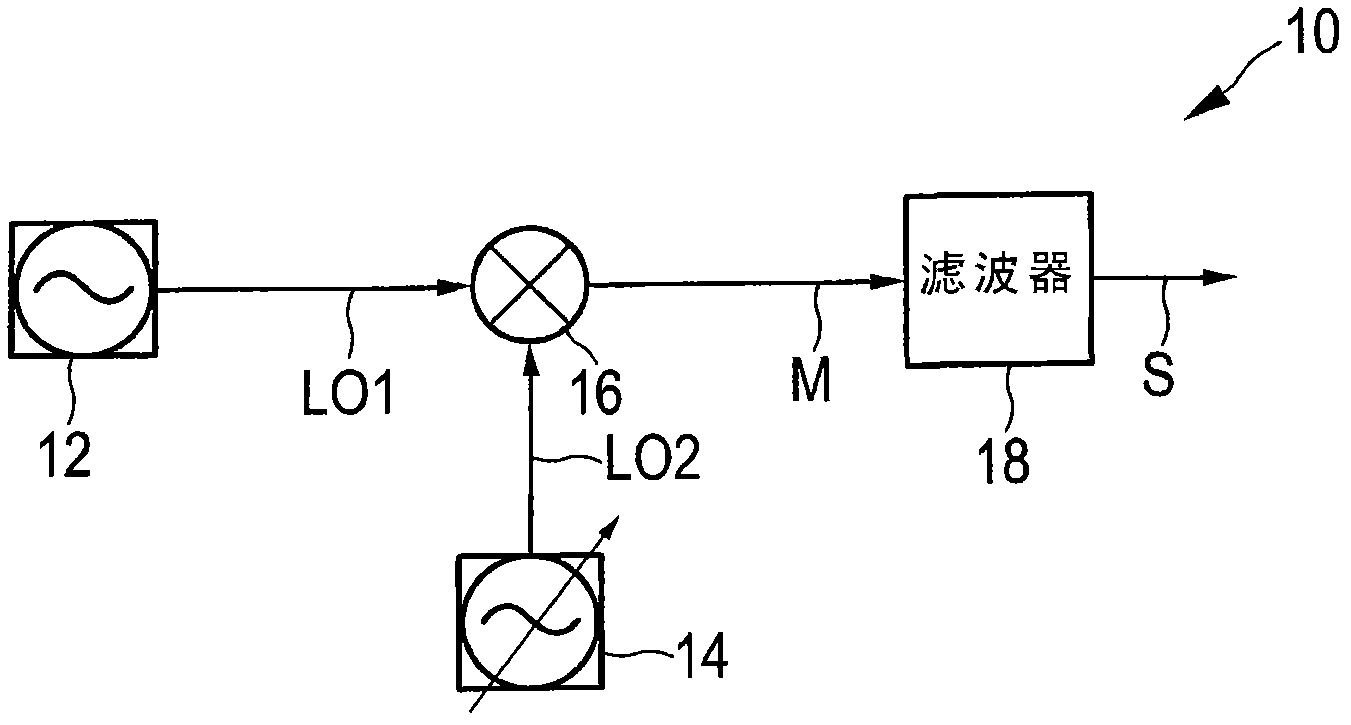
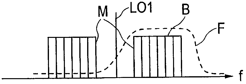
[0026] figure 1 A block diagram of a simple embodiment of a known frequency synthesizer 10 is shown. The frequency synthesizer 10 comprises a first oscillator 12, for example a DRO (Dielectric Resonator Oscillator), which provides a first local oscillator signal LO1 with a fixed (stable) frequency. Furthermore, the frequency synthesizer 10 also includes a second tunable oscillator 14, for example a tunable voltage controlled oscillator (VCO), which provides a second local oscillator signal LO2 with a tunable frequency. The first local oscillator signal LO1 and the second local oscillator signal LO2 are mixed by a mixer 16 to produce a mixer signal M which is filtered by a (preferably switchable) filter 18 to select the synthesizer of the desired frequency band Output signal S. For example, from Dengler, R.J., Cooper, K.B., Llombart, N., Chattopadhyay, G., Bryllert, T., Mehdi, I., Siegel, P.H., “Toward real-time penetrating imaging radar at 670GHz,” Microwave Symposium Digest...


PUM


Abstract

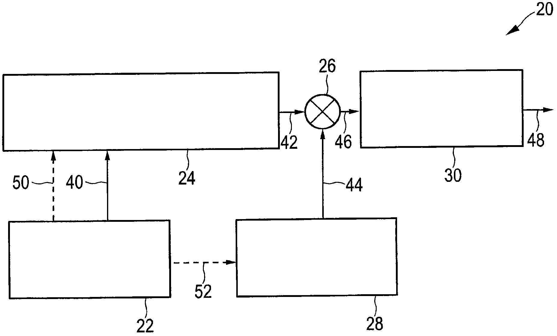
The present invention relates to a FREQUENCY SYNTHESIZER AND a FREQUENCY SYNTHESIZING METHOD, wherein the frequency synthesizer comprises: a reference signal source (22) that provide a first reference signal, a frequency signal generation unit (24) that generates a synthesized frequency output signal at a predetermined frequency, a mixing unit (26) that mixes said synthesized frequency output signal with a frequency tuning signal and outputs a mixer signal, a frequency tuning unit (28) that provides said frequency tuning signal, said frequency tuning unit comprising a first frequency tuning sub-unit (100) and a second frequency tuning sub-unit (102) which alternately provide said frequency tuning signal, wherein, while one of the first and second frequency tuning sub-units is providing the frequency tuning signal, the other of the first and second frequency tuning sub-units is preparing for providing the frequency tuning signal, and a frequency selection unit (30) that selects a desired frequency range from said mixer signal and outputs a frequency synthesizer output signal.

Description

technical field [0001] The invention relates to a frequency synthesizer and a corresponding frequency synthesis method. Background technique [0002] Frequency synthesizers are key building blocks of many microwave systems. They are found in many modern devices including radio receivers, mobile phones, satellite receivers, GPS systems, radars, and the like. There are three main synthesizer architectures, specifically direct analog synthesizers, direct digital synthesizers, and indirect (phase-locked loop) synthesizers. Microwave systems are increasingly demanding such that known synthesizers cannot meet requirements such as phase noise, switching rate, fine resolution and frequency sweep. In recent years, a new hybrid architecture has been developed that combines a direct digital synthesizer (DDS) and a phase-locked loop (PLL), however, it also cannot meet all these requirements. [0003] Millimeter-wave (mm-wave) / sub-THz frequency synthesizers that can generate ultra-wid...

Claims


Application Information

Patent Timeline
Patent Type & Authority Applications(China)
IPC IPC(8): H03L7/18
CPCH03L7/185H03L7/23
Inventor 弗坎·达伊斯特凡·科赫
Owner SONY CORP
Learn More