Welding method for copper back plate and target

A welding method and technology for copper backing, which are applied in welding equipment, non-electric welding equipment, metal processing equipment, etc., can solve the problems of low yield of target components and low welding strength of target components, and achieve welding strength and yield. high effect

Inactive Publication Date: 2012-06-13
KONFOONG MATERIALS INTERNATIONAL CO LTD
View PDF6 Cites 18 Cited by
  • Summary
  • Abstract
  • Description
  • Claims
  • Application Information

AI Technical Summary

Problems solved by technology

However, in the actual production process, it is found that the yield of the target assembly formed by the above-mentioned production p...

Method used


Image

  • Welding method for copper back plate and target
  • Welding method for copper back plate and target

Examples


Embodiment Construction

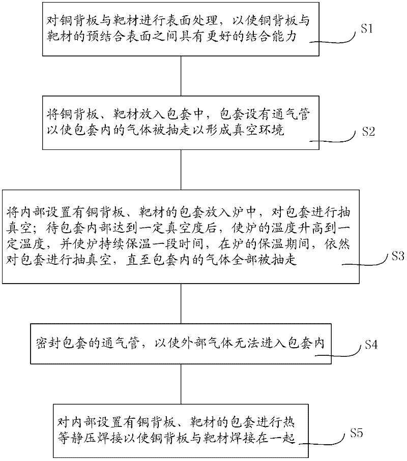
[0022] As mentioned in the background technology, the general production process of welding the copper backplane and the target material together by hot isostatic welding process in the prior art is as follows: put the copper backplane and the target material into the sheath; Vacuumize the package with copper backplate and target material; seal the package so that the outside gas cannot enter the package; perform hot isostatic welding on the package with copper backplate and target material inside to realize Welding of copper backplane and target. After continuous analysis and experiments, the inventor of this case found that the reasons for the lower welding strength and yield of the target assembly formed by the above-mentioned manufacturing method are as follows: In order to have a better bond between the copper back plate and the pre-bonded surface of the target ability, before putting the copper backplane and the target into the package, it is necessary to carry out surfa...


PUM


Abstract

The invention provides a welding method for a copper back plate and a target, comprising the following steps of: placing the copper back plate and the target in a sheath, and disposing a ventilation tube in the sheath; placing the sheath in a furnace, and vacuumizing the sheath via the ventilation tube; after the interior of the sheath achieves a certain vacuum degree, increasing the temperature of the furnace to a certain temperature, continuously insulating the furnace for a period of time, and still vacuumizing the sheath during the insulating period of the furnace; sealing the ventilation tube in the sheath; and performing hot isostatic pressing welding on the sheath provided with the copper back plate and the target in the interior, so as to weld the copper back plate with the target together. During the process of vacuumizing the sheath, the sheath is continuously kept in a high-temperature environment, so that liquid water or other liquids in the interior of the sheath form steam capable of being extracted away, so as to form a real vacuum environment in the interior of the sheath, thereby obtaining a target assembly with high welding strength and yield.

Description

technical field [0001] The invention relates to the field of manufacturing semiconductor sputtering targets, in particular to a welding method for a copper back plate and a target. Background technique [0002] In the semiconductor industry, the target assembly is composed of a target that meets the sputtering performance and a back plate that can be combined with the target and has a certain strength. The back plate can play a supporting role when the target assembly is assembled to the sputtering base, and has the effect of conducting heat. During the sputtering process, the working environment of the target assembly is relatively harsh. For example, the ambient temperature of the target assembly is relatively high, such as 300°C to 600°C; in addition, one side of the target assembly is flushed with cooling water, while the other side is in a high vacuum environment of 10-9Pa, As a result, a huge pressure difference is formed on opposite sides of the target assembly; mor...

Claims


Application Information

Patent Timeline
IPC IPC(8): B23K20/02B23K20/14B23K20/24
Inventor 姚力军潘杰王学泽袁海军
Owner KONFOONG MATERIALS INTERNATIONAL CO LTD
Why Eureka
Try Eureka