Distributed type electronic hydraulic brake system using isolating valves

A hydraulic brake and isolation valve technology, applied in the direction of brakes, brake transmissions, transportation and packaging, etc., can solve the problem of braking deviation and braking stability, causing risks, and failure to meet braking stability and braking performance and other issues to achieve the effect of ensuring braking efficiency and braking stability and improving system reliability

Active Publication Date: 2012-06-13
TSINGHUA UNIV
View PDF4 Cites 10 Cited by
  • Summary
  • Abstract
  • Description
  • Claims
  • Application Information

AI Technical Summary

Problems solved by technology

In this way, there is a problem: for the distributed brake-by-wire system, when a brake actuator fails during the braking process (that is, the brake actuator cannot generate braking force, or can only produce a small unsatisfactory required braking force), if the brake actuator is allowed to fail, it may lead to insufficient overall braking force of the vehicle and affect the braking performance, and at the same time cause the braking force on one side of the vehicle to be greater than the braking force on the other side, resulting in braking Running deviation and decreased braking stability
This method can basically guarantee the braking stability and braking efficiency in the case of low braking intensity and medium braking intensity, but may not meet the requirements of braking stability and braking efficiency in the case of high braking intensity , leading to the risk
[0003] The applicant once proposed a distributed brake-by-wire system: automotive electromechanical hydraulic brake system, the patent number is ZL200920110660.X, its structure is as follows figure 1 As shown, its disadvantage is that if a brake actuator fails during high-intensity braking, the redistribution of braking force by software control strategy alone may not meet the requirements of braking stability and braking efficiency. thereby causing the risk

Method used


Image

  • Distributed type electronic hydraulic brake system using isolating valves
  • Distributed type electronic hydraulic brake system using isolating valves
  • Distributed type electronic hydraulic brake system using isolating valves

Examples


Embodiment Construction

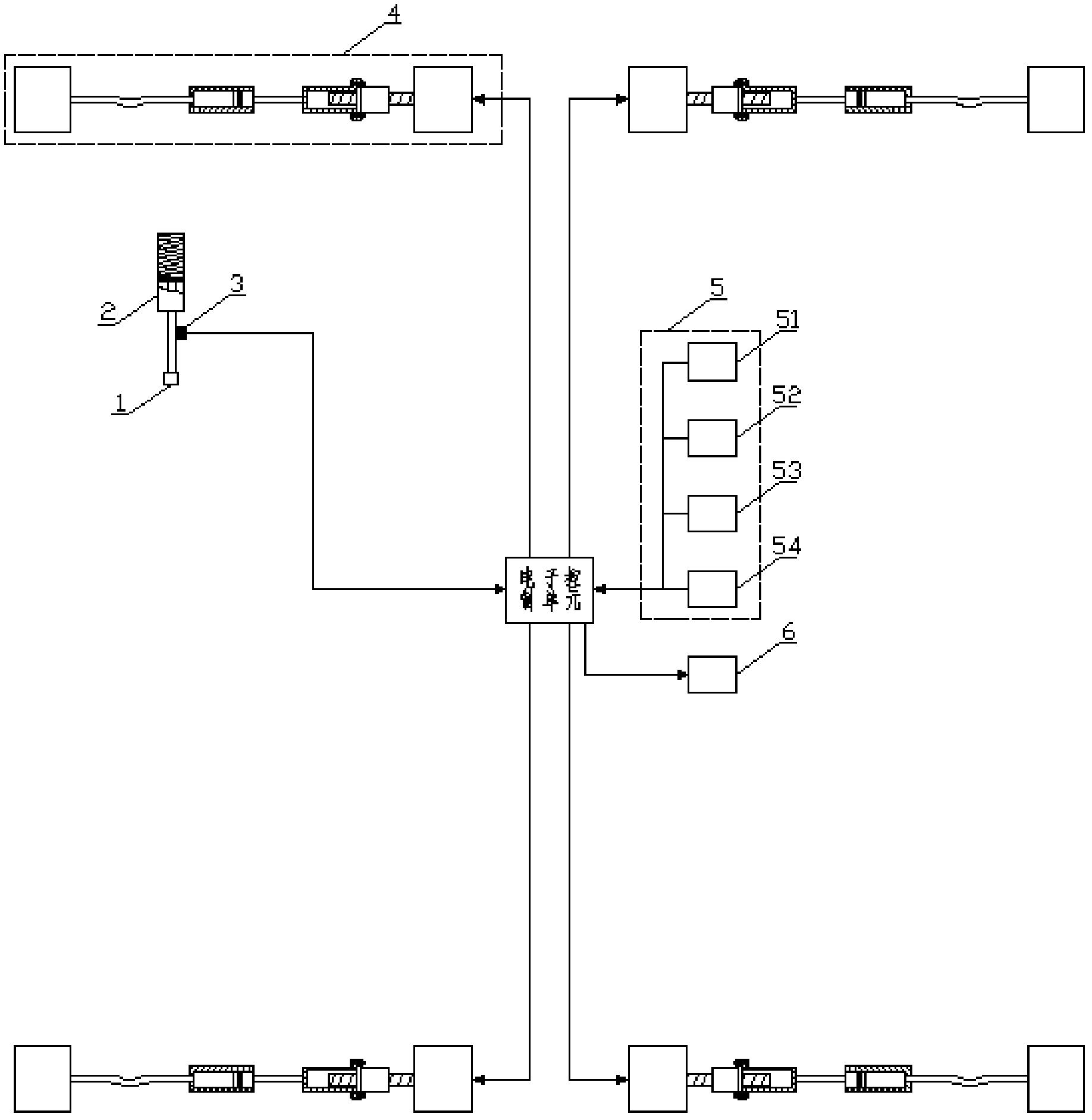
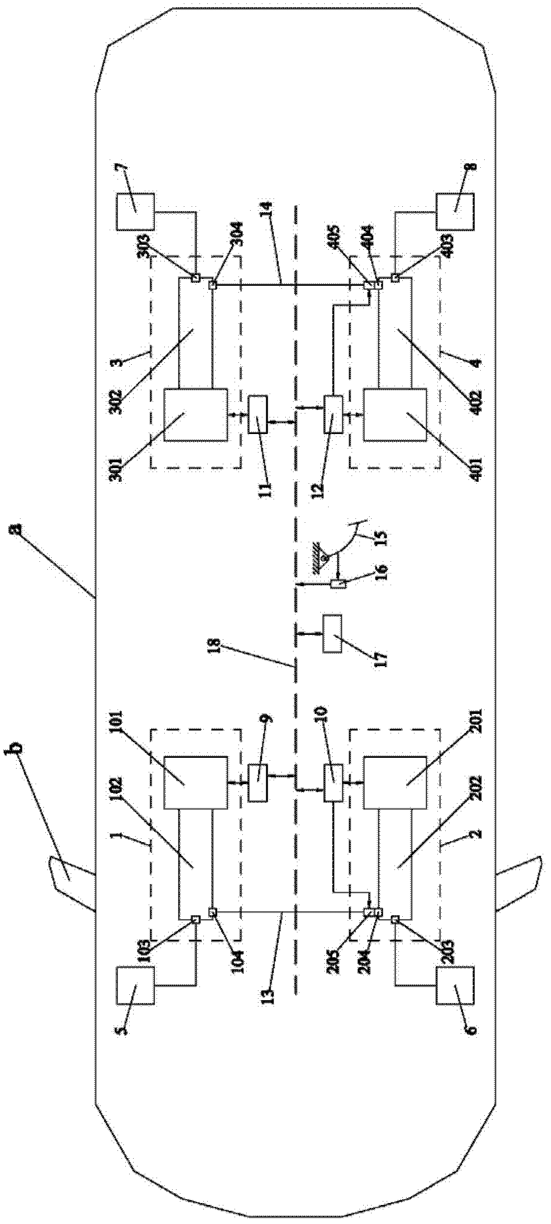
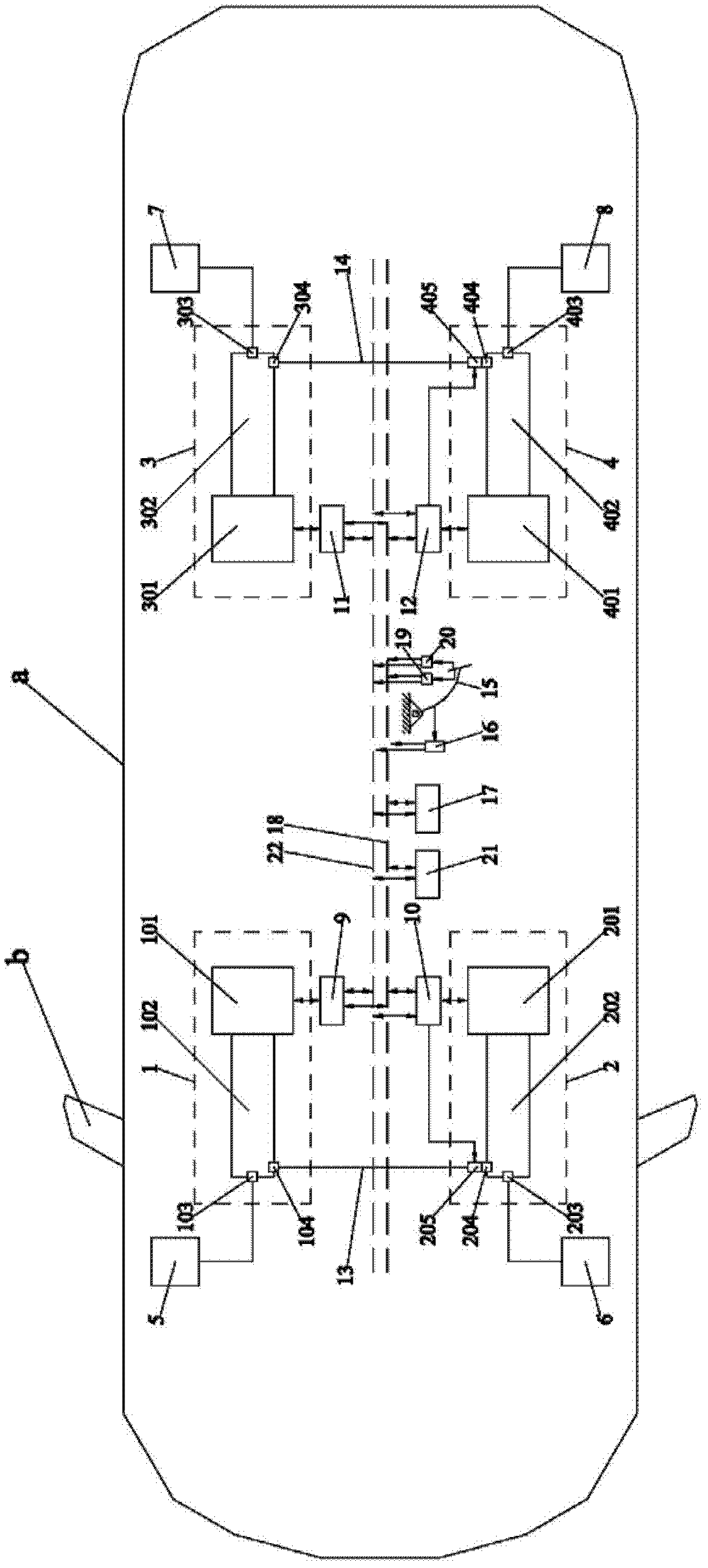
[0011] A distributed electro-hydraulic braking system using an isolation valve proposed by the present invention has a structure such as figure 2 As shown, including right front brake actuator 1, left front brake actuator 2, right rear brake actuator 3, left rear brake actuator 4, right front brake 5, left front brake 6, right rear brake 7, left rear brake 8. Right front brake actuator controller 9, left front brake actuator controller 10, right rear brake actuator controller 11, left rear brake actuator controller 12, brake pedal 15, pedal sensor 16, wire Control the brake controller 17 and the bus 18, which is characterized in that the hydraulic cylinders of the right front brake actuator 1, the left front brake actuator 2, the right rear brake actuator 3 and the left rear brake actuator 4 are respectively provided with There are a first oil outlet and a second oil outlet, and the distributed electronic hydraulic braking system also includes a front axle brake actuator isol...


PUM


Abstract

The invention relates to a distributed type electronic hydraulic brake system using isolating valves and belongs to the field of active safety of automobiles. The distributed type electronic hydraulic brake system comprises four brake actuating mechanisms, four brakes, two isolating valves, four actuating mechanism controllers, a brake pedal, one pedal sensor, a line control brake controller, a bus and a brake pipeline. Each brake actuating mechanism is composed of a motor and a hydraulic cylinder. Each hydraulic cylinder is provided with two oil outlets, one of the two oil outlets is connected with the brakes, and the other oil outlet is connected with the isolating valves. One of the two isolating valves is used for being connected with the brake actuating mechanisms of two front wheels, and the other isolating valve is used for being connected with the brake actuating mechanisms of two rear wheels. The distributed type electronic hydraulic brake system using the isolating valves can improve reliability.

Description

technical field [0001] The invention relates to a distributed electronic hydraulic braking system using an isolation valve, which belongs to the field of automobile active safety. Background technique [0002] Automotive brake-by-wire systems have very high reliability requirements, and technical means such as hardware and software redundancy design, fault diagnosis, and fault-tolerant control are usually used to enhance system reliability. For distributed brake-by-wire systems, redundant design is usually carried out for power supply, pedal sensor, bus, electronic control unit, etc., and system reliability is improved through redundant software and hardware backup. Executing agencies for redundancy design. In this way, there is a problem: for the distributed brake-by-wire system, when a brake actuator fails during the braking process (that is, the brake actuator cannot generate braking force, or can only produce a small unsatisfactory required braking force), if the brake...

Claims


Application Information

Patent Timeline
Patent Type & Authority Applications(China)
IPC IPC(8): B60T13/66
Inventor 王治中于良耀王语风宋健
Owner TSINGHUA UNIV
Why Eureka
Try Eureka