Composite rotor blade for unmanned helicopter and manufacturing method thereof

A technology for unmanned helicopters and rotor blades, which is applied in the field of unmanned helicopter composite rotor blades and its production, can solve the problems of increasing the manufacturing cost of rotor blades, achieve compact structure, reduce the number of molds, and have good shape accuracy Effect

Inactive Publication Date: 2012-06-13
NO 60 RES INST OF GENERAL STAFF DEPT PLA
View PDF5 Cites 39 Cited by
  • Summary
  • Abstract
  • Description
  • Claims
  • Application Information

AI Technical Summary

Problems solved by technology

The biggest disadvantage of manufacturing rotor blades by these methods is that additional molding m

Method used


Image

  • Composite rotor blade for unmanned helicopter and manufacturing method thereof
  • Composite rotor blade for unmanned helicopter and manufacturing method thereof
  • Composite rotor blade for unmanned helicopter and manufacturing method thereof

Examples


Embodiment Construction

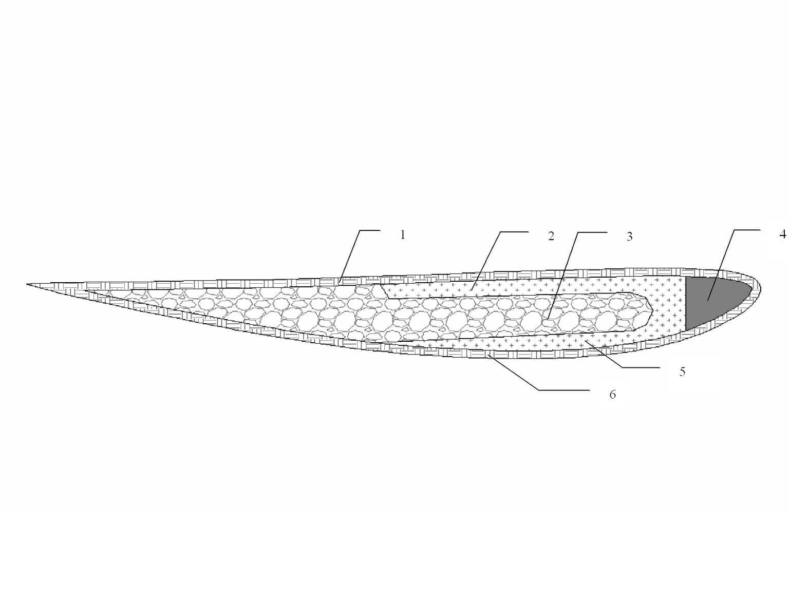
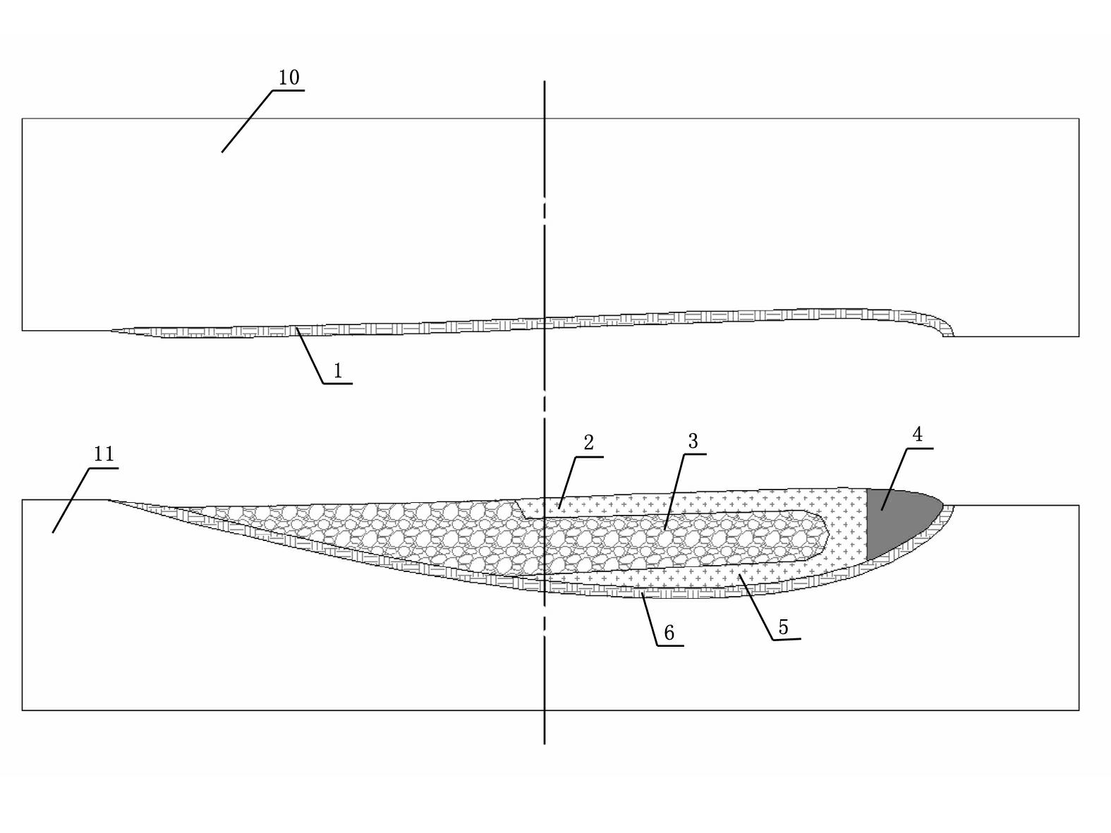
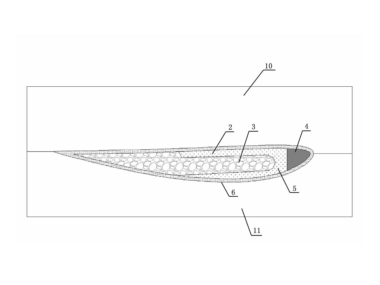
[0031] Refer to attached Figure 1~4 , the unmanned helicopter composite material rotor blade includes an upper airfoil skin 1, a lower airfoil skin 6, an upper airfoil portion 2 of a C-shaped beam, a lower airfoil portion 5 of a C-shaped beam, and a leading edge counterweight lead strip 4, Propeller root bushing 7, foam core 3, propeller tip counterweight lead weight 8 and propeller tip trailing edge counterweight tube 9. as attached figure 1 And attached figure 2 As shown, the upper airfoil skin 1 and the lower airfoil skin 6 are closed to form the shape of the blade. The lower airfoil part 5 of the girder is combined into a C-shaped girder. The C-shaped girder is close to the leading edge counterweight lead strip 4. The rear edge of the C-shaped girder is filled with a foam core 3. For the purpose of adjusting the balance, the front part of the blade is solidified with a tip counterweight. Lead block 8 and weight tube 9 at the trailing edge of the blade tip, and a blade...


PUM


Abstract

The invention relates to a composite rotor blade for an unmanned helicopter and a manufacturing method thereof. The composite rotor blade comprises an upper airfoil skin, a lower airfoil skin, an upper airfoil part of a C-shaped crossbeam, a lower airfoil part of the C-shaped crossbeam, a leading edge balance weight lead strip, a paddle root lining, a foam core, a paddle tip balance weight lead block and a balance weight pipe, wherein the upper airfoil skin and the lower airfoil skin are closed to form the profile of a blade; the leading edge balance weight lead strip is arranged on the leading edge of a blade airfoil profile; the upper airfoil part of the C-shaped crossbeam and the lower airfoil part of the C-shaped crossbeam are combined to form the C-shaped crossbeam; the C-shaped crossbeam is close to the leading edge balance weight lead strip; the foam core is filled into a trailing edge part of the C-shaped crossbeam; and in order to regulate balance, the paddle tip balance weight lead block and the paddle tip trailing edge balance weight pipe are cured on the front section of the blade, and the paddle root lining is arranged on the rear section of the blade.

Description

technical field [0001] The invention relates to an unmanned helicopter composite rotor blade and a manufacturing method thereof. Background technique [0002] The traditional composite material rotor blade is to lay the skin on the upper and lower mold cavities of the rotor blade forming mold, and the beam of the rotor blade is preformed by laying prepreg tape on an independent mold, or preformed by winding. After a large amount of preforming is completed, take out the girder and assemble it on the skinned rotor blade forming mold, then place the counterweight components, then lay the foam core or honeycomb core, and then close the mold to solidify the rotor blade. After the rotor blades are solidified, take out the rotor blades, do the pre-glue treatment on the leading edge, and paste the iron-clad leading edge on another special mold through secondary cementation. Some manufacturing methods are to preform the girder on an independent mould, then solidify and form, and fin...

Claims


Application Information

Patent Timeline
IPC IPC(8): B64C27/46B29C51/02B29C51/12B29C51/14
Inventor 姜年朝张逊张志清戴勇周福亮宋军尚其龙焦志文
Owner NO 60 RES INST OF GENERAL STAFF DEPT PLA
Why Eureka
Try Eureka