
Support leg disc, support device and engineering vehicle

A support device and foot plate technology, which is applied in vehicle maintenance, lifting vehicle accessories, transportation and packaging, etc., can solve problems such as stress concentration, contact area reduction, deformation, etc.

Active Publication Date: 2012-06-13
ZOOMLION HEAVY IND CO LTD
View PDF9 Cites 6 Cited by
  • Summary
  • Abstract
  • Description
  • Claims
  • Application Information

AI Technical Summary

Problems solved by technology

However, when this kind of foot plate bears a large load, it will deform, resulting in a decrease in the effective contact area with the ground and stress concentration.
Therefore, the existing foot plate is difficult to meet the design requirements under heavy load conditions

Method used


Image

  • Support leg disc, support device and engineering vehicle
  • Support leg disc, support device and engineering vehicle
  • Support leg disc, support device and engineering vehicle

Examples


Embodiment Construction

[0030] Specific embodiments of the present invention will be described in detail below in conjunction with the accompanying drawings. It should be understood that the specific embodiments described here are only used to illustrate and explain the present invention, and are not intended to limit the present invention.

[0031] In the present invention, in the case of no contrary description, the used orientation words such as "upper and lower" refer to the upper and lower sides of the foot plate of the present invention in use, which is consistent with the direction shown in the accompanying drawings; Direction" usually refers to the radial direction of the center hole on the base plate of the foot plate of the present invention; The side of the center of the central hole) is the inner side, and the side of the support plate facing the edge of the bottom plate (that is, the periphery of the central hole) is the outer side. It should be noted that, for the arched support plate ...


PUM


Abstract

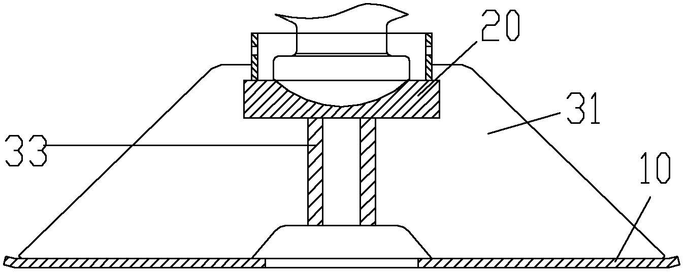
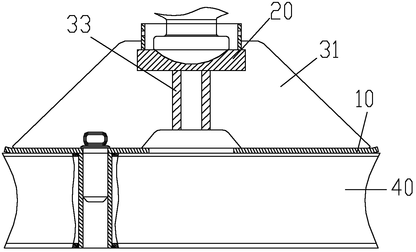
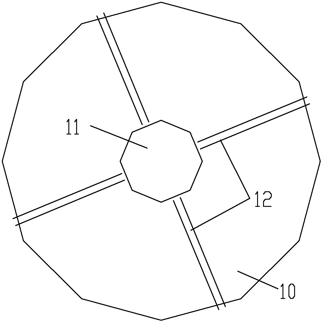
The invention discloses a support leg disc, which comprises a bottom plate (10), a ball head concave seat (20) and a support plate, wherein the center of the bottom plate (10) is provided with a center hole (11), the lower side edge of the support plate is fixedly arranged on the bottom plate (10) in the radial direction, and the ball head concave seat (20) is fixedly arranged on the upper side edge of the support plate. Through the technical scheme, the center hole is arranged in the bottom plate of the support leg disc, so a born vertical load is transmitted to the bottom plate in an inclined way. Through the structure, the effective carrying area is enlarged, in addition, the profit distribution is uniform, and simultaneously, the gyroscopic moment transmitting capability is improved.

Description

technical field [0001] The invention relates to the field of engineering machinery, in particular to a foot plate. In addition, the present invention also relates to a supporting device and an engineering vehicle using the foot plate. Background technique [0002] During the operation of construction machinery, in order to maintain balance and support loads, support structures such as outriggers are usually used. The ends of the outriggers are connected with outrigger plates, and the outriggers contact the ground through the outrigger plates. The support foot plate mainly plays the roles of reducing the pressure of the support legs to the ground and increasing the frictional force between the support legs and the ground. Because the load of large-scale construction machinery is usually large, such as a super-large-tonnage crane, the weight and load capacity of the whole machine are relatively large, so the turning moment of the whole vehicle during work is very large, which...

Claims


Application Information

Patent Timeline
IPC IPC(8): B66C23/78B60S9/02
Inventor 詹纯新刘权张建军张良
Owner ZOOMLION HEAVY IND CO LTD
Learn More