Force-bearing disk squeezing and expanding machine

A technology of extruding and expanding machine and bearing plate, which is applied in the direction of fluid pressure actuating device, sheet pile wall, building, etc. Effective bearing area, avoid the increase of manufacturing cost, and improve the effect of bearing capacity

Inactive Publication Date: 2011-01-12
韩顺和 +1
View PDF0 Cites 0 Cited by
  • Summary
  • Abstract
  • Description
  • Claims
  • Application Information

AI Technical Summary

Problems solved by technology

[0005] The problem with this structure is that the thrust output by the hydraulic cylinder is limited by the pressure of the hydraulic system. When encountering hard or viscous soil during construction, the extrusion and expansion construction cannot be realized due to excessive resistance, which limits the pressure of the bearing plate. The application of extrusion machine; due to the limited extrusion force, the length of the extrusion arm is limited, which is not conducive to increasing the diameter of the disc and the effective bearing area, thus limiting the bearing capacity of the extruded branch pile
[0006] Since the thrust output by the hydraulic cylinder is limited by the pressure of the hydraulic system, on the premise that the pressure of the hydraulic system is constant, on the one hand, in order to increase the thrust output by the hydraulic cylinder, the working area of ​​the piston must be increased, that is, the diameter of the piston must be increased. Enlarging the structural size of the piston and the oil cylinder will lead to an increase in the size of the load-bearing disc extruder, increase the manufacturing cost, inconvenient use, and bring difficulties to transportation and construction; on the other hand, if the structural size of the oil cylinder is not changed, in order to improve The thrust output by the hydraulic cylinder requires the use of a higher-pressure oil pump, which also leads to an increase in production costs. In addition, due to the use of a high-pressure pump, the pressure of the hydraulic system increases, causing the seal of the hydraulic cylinder to leak easily. Therefore, higher requirements are put forward for the sealing structure. Require

Method used

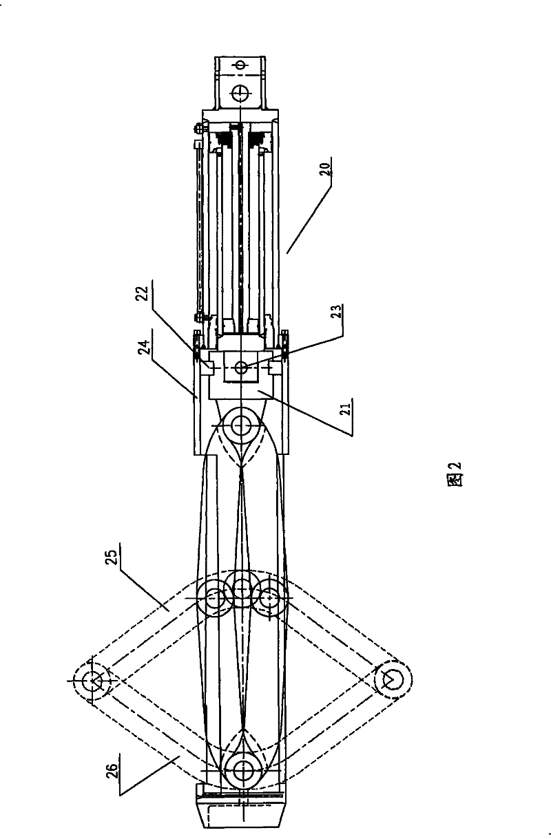
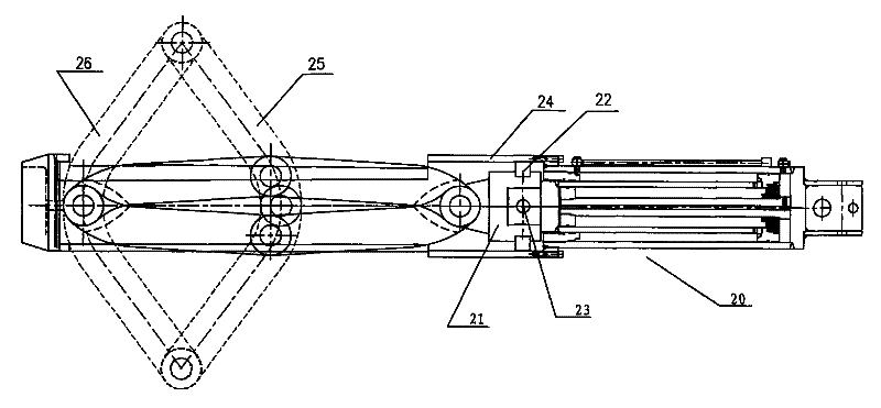

Image

  • Force-bearing disk squeezing and expanding machine
  • Force-bearing disk squeezing and expanding machine
  • Force-bearing disk squeezing and expanding machine

Examples


Embodiment Construction

[0024] The present invention will be described in detail below with reference to specific examples.

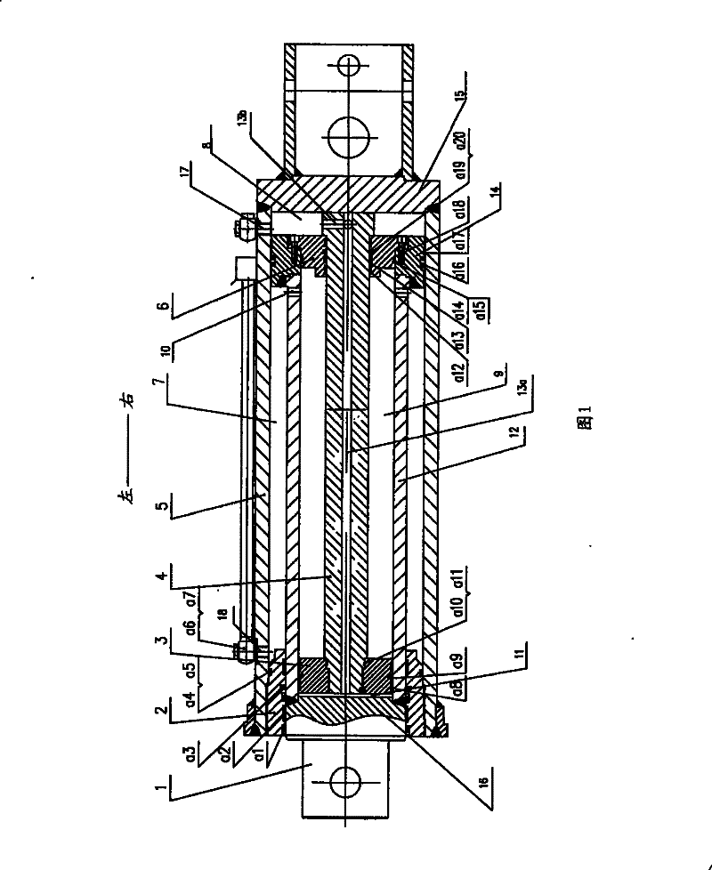
[0025] Such as figure 1 as shown, figure 1 It is a longitudinal sectional view of the booster oil cylinder in the bearing disc extruder of the present invention. The booster oil cylinder comprises a cylindrical cylinder body 5, the cylinder body 5 has two ends opposite to each other in the axial direction, one end is closed by the cylinder head 15 by being welded into one with the cylinder head 5, and the other end is provided with a large body fixed therewith. The guide sleeve 2 and the outer surface of the large guide sleeve 2 and the inner surface of the cylinder body 5 are provided with an O-ring retaining ring a4 and an O-ring sealing ring a5.

[0026] A large piston rod 1 that is substantially coaxial with the cylinder body 5 is provided. The large piston rod 1 includes a large piston rod main body 12 and a connecting portion 16. The large piston rod main body 12 is cy...


PUM


Abstract

The present invention provides one kind of bearing disc extruding and expanding machine comprising one support, one forming mechanism and one hydraulic cylinder. The forming mechanism includes two sets of arched pressing arms set axially symmetrically hinged to the support and driven by the hydraulic cylinder, and each of the arched pressing arm set consists of one pair of branch arms. The hydraulic cylinder includes one cylinder, one first piston assembly reciprocating axially inside the cylinder and one second piston assembly reciprocating relatively to the first piston assembly, with the second piston assembly possessing one piston rod penetrating the piston of the first piston assembly. The bearing disc extruding and expanding machine has forming mechanism with obviously raised extruding and expanding capacity.

Description

technical field [0001] The invention relates to a device for forming piles for foundation engineering, in particular to an extruding and expanding machine for forming bearing plates of piles for foundation engineering. Background technique [0002] In the existing foundation engineering construction, the method of forming a pile with a load-bearing plate is: firstly, a drilling machine is used to cut the soil body in the foundation to form a pile body hole, and then the load-bearing plate squeezer is lowered into the pile hole. In the appropriate position, the forming mechanism applies lateral extrusion force to the soil around the pile hole to extrude a disk-shaped space on the side of the pile hole, and a plurality of such disk-shaped spaces can be set along the vertical direction of the pile hole. The pile formed after pouring concrete into the pile hole with a disc-shaped space on the side is called an extruded and expanded branch pile. Compared with ordinary cast-in-sit...

Claims


Application Information

Patent Timeline
Patent Type & Authority Patents(China)
IPC IPC(8): F15B15/17E02D5/44
Inventor 韩顺和张晓玲
Owner 韩顺和
Why Eureka
Try Eureka