Crane back-tilting-preventing device with changeable gravity center and crane comprising crane back-tilting-preventing device
A crane and anti-backward tilting technology, which is applied to cranes and other directions, can solve the problems of high cost and complicated structure of the backward tilting device, and achieve the effects of simple structure, easy installation and cost saving.
- Summary
- Abstract
- Description
- Claims
- Application Information
AI Technical Summary
Problems solved by technology
Method used
Image

Examples
Embodiment Construction
[0021] The present invention will be explained in detail below in conjunction with the accompanying drawings and embodiments.
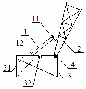
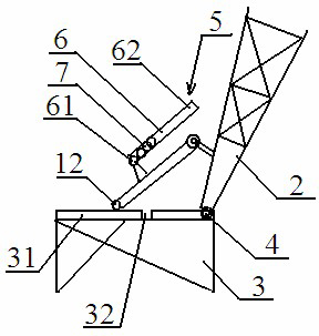
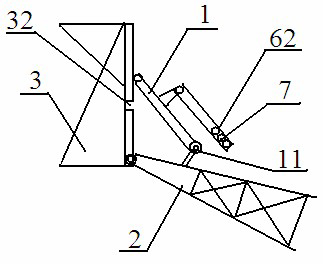
[0022] Such as figure 1 The crane anti-rolling device with a variable center of gravity of the preferred embodiment of the present invention includes a support rod 1, a lower section arm 2 and a tower arm tip 3, and the lower section arm 2 and the tower arm tip 3 pass through the first hinged end 4 hinged.
[0023] The support rod 1 includes a second hinged end 11 and a sliding end 12 , and the second hinged end 11 is rotatably hinged to the lower joint arm 2 .
[0024] A slideway 31 and a groove 32 are provided on the tower arm tip 3 . The sliding end 12 of the support rod 1 is in contact with the slideway 31 and can slide on the slideway 31 . The groove 32 is provided between the sliding end 12 and the first hinged end 4 , and the distance between the sliding end 12 and the first hinged end 4 is greater than or equal to the distance between the g...
PUM
 Abstract
Description
Claims
Application Information
 - R&D
- Intellectual Property
- Life Sciences
- Materials
- Tech Scout
- Unparalleled Data Quality
- Higher Quality Content
- 60% Fewer Hallucinations
Browse by: Latest US Patents, China's latest patents, Technical Efficacy Thesaurus, Application Domain, Technology Topic, Popular Technical Reports.
© 2025 PatSnap. All rights reserved.Legal|Privacy policy|Modern Slavery Act Transparency Statement|Sitemap|About US| Contact US: help@patsnap.com