Driving sink roller drive system

A technology of transmission system and sinking roller, which is applied in the direction of coating, metal material coating process, hot-dip coating process, etc., can solve the problem of failure to put into large-scale industrial production, difficulty in transmitting driving torque, and zinc slag granular stirring There are many problems such as zinc liquid, so as to reduce the capital occupation of spare parts, eliminate or reduce scratches or roll marks, and reduce the effect of changing rolls

Inactive Publication Date: 2012-06-13
BAOSTEEL ENG & TECH GRP
View PDF4 Cites 4 Cited by
  • Summary
  • Abstract
  • Description
  • Claims
  • Application Information

AI Technical Summary

Problems solved by technology

[0007] 1. The sinking roller driven by the inclination angle of the universal joint, because the sinking roller sinks deep into the liquid surface, often exceeding 1000mm, the inclination angle of the universal joint is relatively large, reaching or exceeding the limit of the inclination angle of the joint, and it is difficult to transmit the driving torque; also, the universal joint The inclination angle rotation of the roll surface makes the zinc liquid surface stir up and down, and the zinc slag is stirred into the zinc liquid in a granular form, and the newly stirred zinc liquid surface is constantly oxidized, and the liquid oxidation is relatively large, and the universal joint itself is difficult to lubricate in the high-temperature zinc liquid. Difficult to apply

Method used


Image

  • Driving sink roller drive system
  • Driving sink roller drive system
  • Driving sink roller drive system

Examples


Embodiment Construction

[0028] The present invention will be described in detail below in conjunction with the accompanying drawings and embodiments.

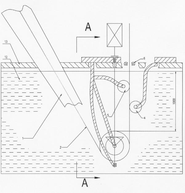
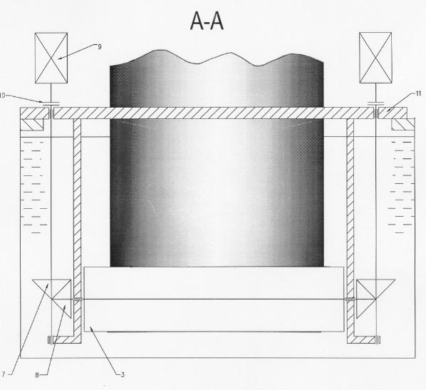
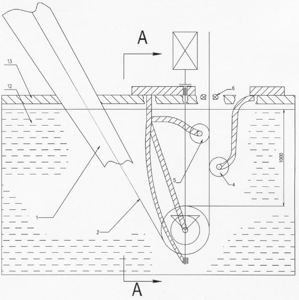
[0029] see figure 1 with figure 2, the present invention provides an active sinking roll transmission system for continuous hot-dip galvanizing production of strip steel, the transmission system is mainly driven by the drive shaft bevel gear assembly 7, the sinking roll bevel gear assembly, the frame assembly 11, and the drive shaft The motor 9 and the shaft coupling 10 are composed. Among them, the sinking roller bevel gear assembly includes the sinking roller 3 and the sinking roller bevel gear 8 assembling to form a rigid integral roller shaft; the frame assembly 11 includes the driving shaft support arm and bearing seat, the sinking roller support arm and bearing seat and the rear stabilizing roller Support arm and bearing housing assembly.

[0030] The drive shaft bevel gear assembly 7 is to be assembled together with the bearing block of the...


PUM


Abstract

The invention relates to a driving sink roller drive system which is used for performing hot-dip galvanizing on band steel. A sink roller bevel gear assembly is arranged in the drive system; and a driving shaft bevel gear assembly is assembled with a bearing block of a driving shaft supporting arm of a frame assembly above a sink roller in a zinc pot in the direction which is vertical to that of a zinc liquid level. A shaft end above the driving shaft bevel gear assembly is connected with a driving shaft driving motor through a coupler to form a rigid integral shaft. A bevel gear below the driving shaft bevel gear assembly is meshed with a bevel gear at the end of the sink roller bevel gear assembly; and a sink roller bevel gear assembly shaft is fixed in the bearing block of a sink roller supporting arm of the frame assembly and is driven by the driving shaft driving motor to rotate. The sink roller is driven by axial driving of the bevel gears. A driving shaft is input in the direction vertical to the liquid level of the zinc pot, and the bevel gear at the end of the driving shaft drives the bevel gear at the end of the sink roller so as to drive the sink roller to rotate at speed which is the same as that of the band steel, so the friction between the band steel and the surface of the sink roller is basically eliminated; and therefore, scratching or roll marks are eliminated or reduced from a source.

Description

technical field [0001] The invention relates to hot-dip galvanizing production line equipment, in particular to a drive system for active sinking rolls. Background technique [0002] Hot-dip galvanizing is that the strip steel enters the zinc pot through the furnace nose for galvanizing after continuous annealing and cooling, passes through the sinking roll and stabilizing roll in the zinc pot, controls its exit from the zinc pot, and blows off the excess zinc liquid by the air knife. The cooling air box cools down and forms a uniform coating on the surface of the strip. But there are following problems: [0003] The strip at the hot-dip galvanized sinking roll needs a reasonable strip unit tension, because the strip comes out of the turning roll in the furnace and enters the zinc pot through the furnace nose, whether it is in the furnace or in the furnace nose or in the zinc pot, All in the closed high-temperature body, at this time the strength of the strip steel is grea...

Claims


Application Information

Patent Timeline
IPC IPC(8): C23C2/06C23C2/40
Inventor 张云川
Owner BAOSTEEL ENG & TECH GRP
Why Eureka
Try Eureka