
Glove knitting machine with electronic pneumatic control type piston needle selection device

A technology with electronics and glove machine, applied in the field of glove machine, can solve the problems of affecting fabric output, slow machine running speed, and limited number of patterns, etc., and achieve the effect of diversification of fabrics and fabric patterns, and rapid needle selection

Inactive Publication Date: 2013-07-31
丁原章
View PDF7 Cites 0 Cited by
  • Summary
  • Abstract
  • Description
  • Claims
  • Application Information

AI Technical Summary

Problems solved by technology

[0003] However, due to the limited outer diameter and installed space of the aluminum drum of ordinary glove machines, the number of horizontal grooves on the outer diameter of the aluminum drum is limited, and the number of needle selection arrangements, the type of fabric and the size of the fabric are limited. The number of patterns is also limited
Although the existing jacquard glove machine that selects needles by the electronic needle selector installed in the head of the glove machine solves the above problems, the stability of the electronic needle selector inside the machine head is unstable because the machine head runs back and forth. It is not guaranteed, and the electronic components such as connected wires are not necessarily very safe; the machine runs at a relatively slow speed, which affects the output of the fabric produced

Method used


Image

  • Glove knitting machine with electronic pneumatic control type piston needle selection device
  • Glove knitting machine with electronic pneumatic control type piston needle selection device
  • Glove knitting machine with electronic pneumatic control type piston needle selection device

Examples


Embodiment Construction

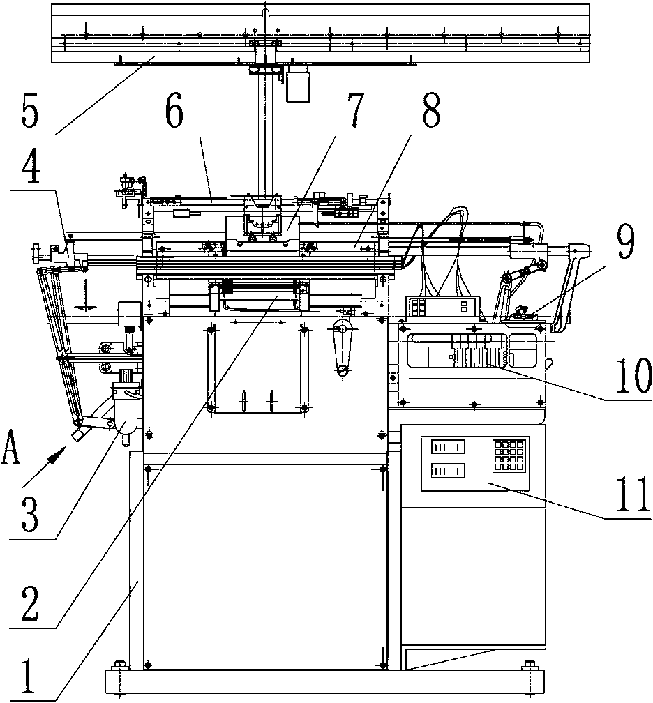
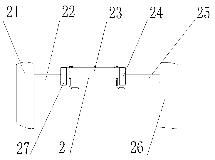
[0025] Please refer to the attached figure 1 to attach Figure 8 As shown, the present invention is a glove machine with an electronic air-controlled piston needle selection device, which consists of a frame part 1, a needle selection part 2, an air control part 3, a fork knife and scissors part 4, a creel part 5, The yarn delivery part 6, the head part 7, the needle plate part 8, the lubricating system part 9, the transmission part 10 and the computer control part 11 are composed of several parts.

[0026] Wherein, the needle selection component 2 is installed on the frame component 1 . The needle plate part 8 is arranged corresponding to the needle selection part 2, so that the needle selection part 2 drives the needle plate part 8 to perform needle selection. Described needle board part 8 is divided into two parts, front needle board part and rear needle board part, respectively correspondingly installed in the front and rear positions of machine head part 7 below.

[00...


PUM


Abstract

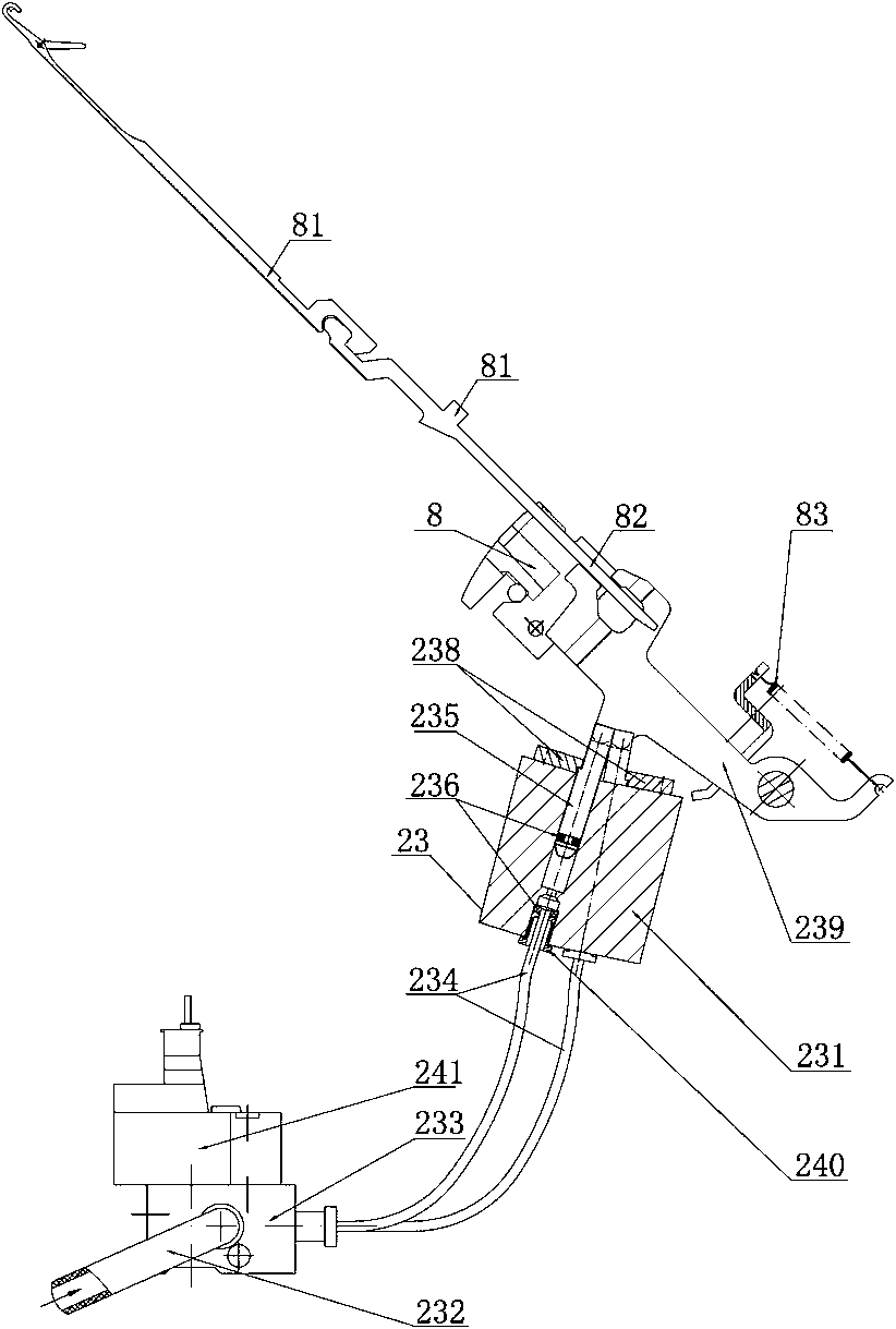
The invention relates to a glove knitting machine with an electronic pneumatic control type piston needle selection device, which is composed of a frame component, a needle selection component, a pneumatic control component, a creel component, a machine head component, a needle plate component, a computer control component and the like. A needle selection device is arranged on the needle selection component and comprises a needle selection seat, a main air pipe, a converging body, a plurality of branch air pipes, pistons, a stopping plate and a bird sheet. A plurality of hole groups are arranged on the needle selection seat, one end of the converging body is connected with the main air pipe, the other end of the converging body is connected with the plurality of branch air pipes, each branch air pipe is connected with the bottom of each hole group through a fixing connector, the pistons are contained in the hole groups, the tops of the pistons abut against the bird sheet and push the bird sheet to rotate, and the stopping plate is arranged on the needle selection seat and can adjust the rising height of the pistons. The glove knitting machine can conduct irregular needle selectionunder control of electronic pneumatic control, enables fabric and fabric patterns of the machine to be diversified, and enables the needle selection to be rapid, stable, reliable and free of influences of running of a machine head.

Description

technical field [0001] The invention relates to a glove machine, in particular to a glove machine with an electronic air-controlled piston needle selection device, which belongs to the technical field of knitting machinery. Background technique [0002] There are usually two needle selection methods for existing glove machines: one is the pins installed on different positions of the aluminum roller under the needle plate of the ordinary glove machine, and the bird piece of the glove machine on the corresponding position is lifted with the rotation of the aluminum roller. , so as to achieve the purpose of needle selection; the other is to select needles in the jacquard glove machine by means of an electronic needle selector (thread bag type) installed in the head of the glove machine. [0003] However, due to the limited outer diameter and installed space of the aluminum drum of ordinary glove machines, the number of horizontal grooves on the outer diameter of the aluminum dr...

Claims


Application Information

Patent Timeline
Patent Type & Authority Patents(China)
IPC IPC(8): D04B7/34D04B15/68
Inventor 丁原章
Owner 丁原章
Learn More