Self-stirring type dredging device for river channels

A stirring, river channel technology, applied in construction, earth mover/shovel, etc., can solve problems such as restricting agricultural industrial structure, frequent replacement, affecting agricultural industrial structure, etc., to improve flood control and drought resistance, and reduce sedimentation. , the effect of good economic benefits

Inactive Publication Date: 2012-06-13
SHANDONG UNIV
View PDF15 Cites 4 Cited by
  • Summary
  • Abstract
  • Description
  • Claims
  • Application Information

AI Technical Summary

Problems solved by technology

At the same time, due to the reduction of the irrigation storage capacity of the irrigation area, the cost of using agricultural machinery to irrigate crops has been greatly increased.
[0005] 2) Restricted the adjustment of agricultural industrial structure
Due to the continuous decline in the water capacity of the irrigation area, the implementation of the agricultural industrial structure adjustment plan has been seriously affected
[0006] 3) Water and soil conservation is weakened
[0008] (1) High power, high energy consumption, shallow dredging, generally can only dig loose silt and soil layers with a depth of 5 to 15 meters;
[0009] (2) There are many rotating components, such as bucket wheels, reamers and sand pumps, which are severely worn, frequently replaced, require large maintenance, high operating costs, and complex equipment management;
[0010] (3) Using mechanical bucket wheels and reamers to break the underwater soil and rock will easily damage the channel foundation, cause hidden dangers to channel safety, and deteriorate water quality and pollute the environment
Not only that, using mechanical methods to transport the silt out of the original riverbed has low work efficiency and high cost, and it is impossible to solve the problem of dredging large areas of water; moreover, the cleared silt occupies a large amount of cultivated land and seriously damages the ecology

Method used


Image

  • Self-stirring type dredging device for river channels
  • Self-stirring type dredging device for river channels
  • Self-stirring type dredging device for river channels

Examples


Embodiment Construction

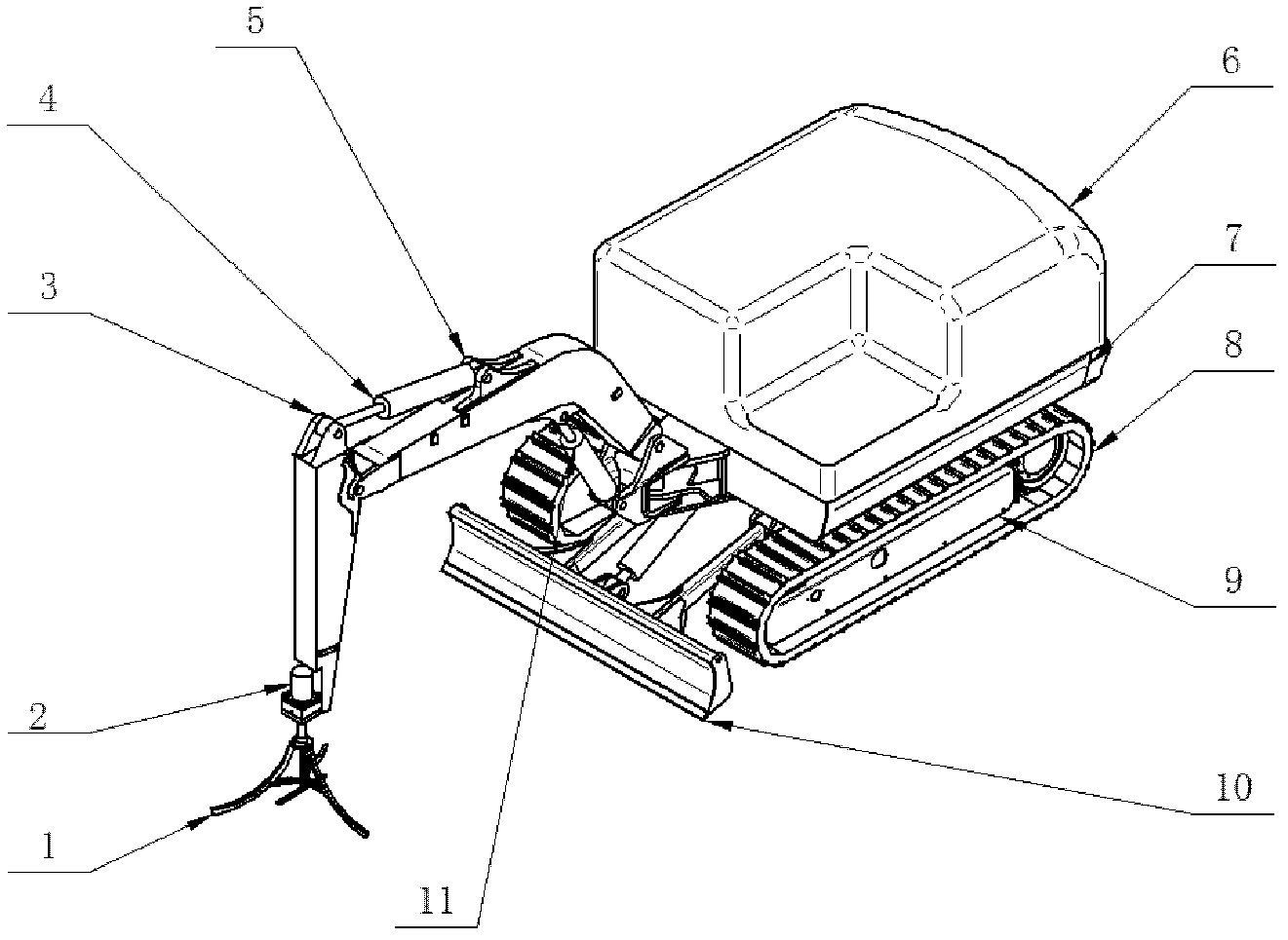
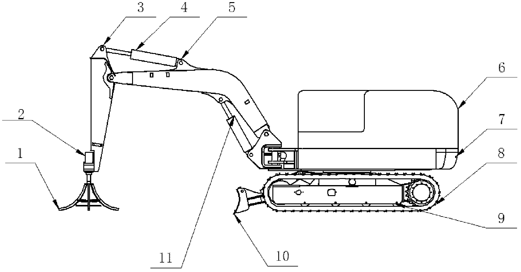
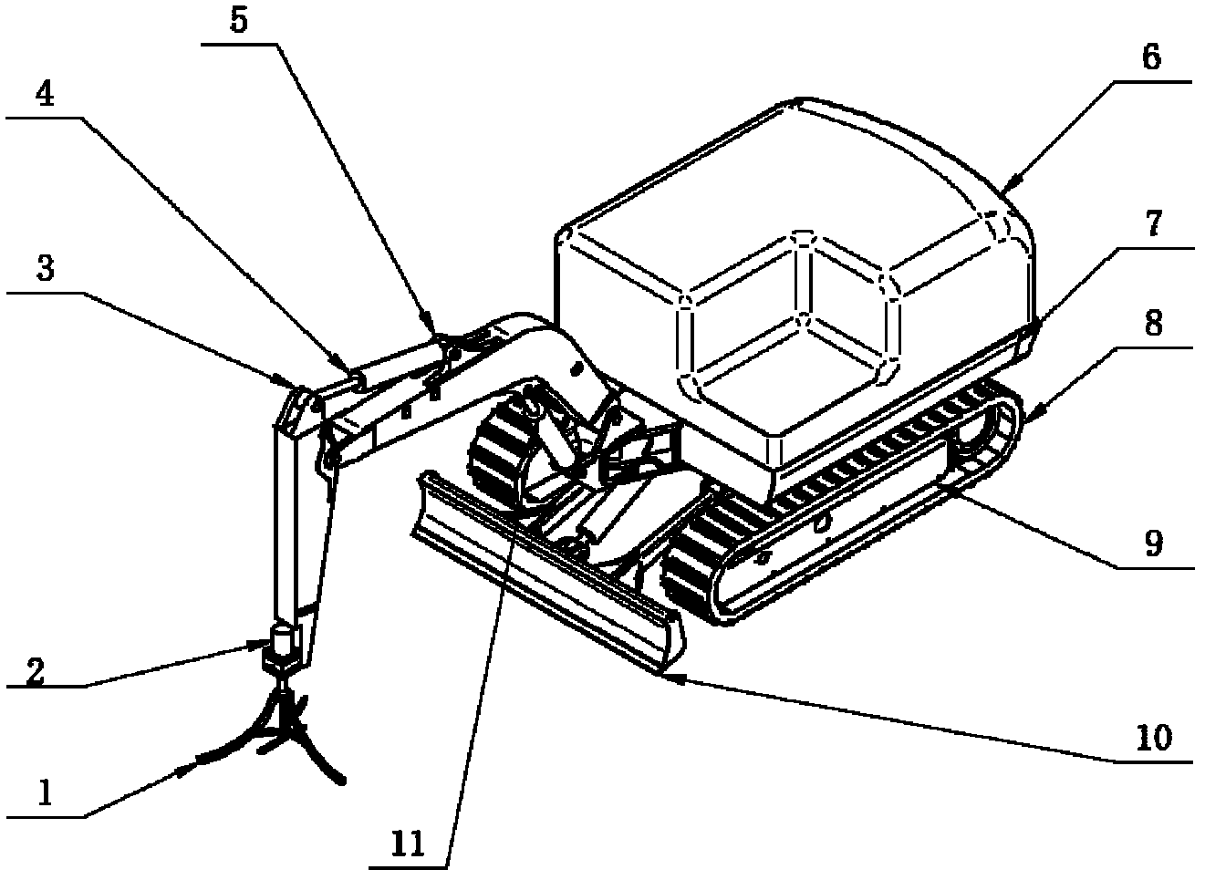
[0025] The present invention will be further described below in conjunction with the accompanying drawings and embodiments.

[0026] Such as figure 1 , 2 As shown, the present invention combines the rotary stirring device 1 with the technology of crawler excavators and underwater walking robots for full reference. It includes: rotating stirring device 1, rotating hydraulic motor 2, stick assembly 3, stick cylinder 4, boom assembly 5, closed power assembly 6, main frame assembly 7, rubber track 8, walking assembly 9. Bulldozing device 10, boom cylinder 11, the main frame assembly 7 is installed on the travel assembly 9, rubber crawlers 8 are installed on both sides of the travel assembly 9, and the closed power assembly 6 is installed on the main frame assembly 7 Above, the stick assembly 3 is hinged with the boom assembly 5, the stick cylinder 4 is hinged with the stick assembly 3 and the boom assembly 5 respectively, the boom assembly 5 is hinged with the front end of the m...


PUM


Abstract

The invention relates to a self-stirring type dredging device for river channels; the self-stirring type dredging device comprises a main frame assembly which is arranged on a walking assembly; rubber tracks are arranged at the two sides of the walking assembly; a closed type power assembly is arranged on the main frame assembly; a movable arm assembly is articulated at the front end of the main frame assembly; a movable arm oil cylinder is articulated between the main frame assembly and the movable arm assembly; the front end of the movable arm assembly is articulated with a bucket rod assembly; a bucket rod oil cylinder is articulated between the bucket rod assembly and the movable arm assembly; a rotary stirring device is fixed at the front end of the bucket rod assembly; a rotary hydraulic motor is fixedly connected on the rotary stirring device; a bulldozing device is arranged at the front end of the walking assembly; and the movable arm oil cylinder, the bucket rod oil cylinder, the rotary hydraulic motor and the bulldozing device are controlled by the closed type power assembly. The self-stirring type dredging device is flexible, efficient and safe.

Description

technical field [0001] The invention relates to the field of water conservancy engineering, in particular to a self-stirring river channel dredging equipment. Background technique [0002] The Yellow River is the birthplace of Chinese culture, and its water is the main source of water in Northwest and North China. "Storing abundant water for dry use, winter storage for spring use, and scientifically citing the Yellow River water" is the basic water regime in Jinan City and even Shandong Province in response to the ten-year drought, the Yellow River cut-off, and the abandonment of water into the sea. The uneven distribution of water in the Yellow River in time and space is a great initiative to promote the harmonious development of man and nature; the Yellow River irrigation canal is one of the important components. [0003] Due to the serious siltation and abandonment of the sedimentation ponds in the Yellow River irrigation area, it has brought a series of serious impacts ...

Claims


Application Information

Patent Timeline
Patent Type & Authority Applications(China)
IPC IPC(8): E02F5/28
Inventor 李建勇任秀华张超李剑峰苏红鲁秦顺顺吕禹
Owner SHANDONG UNIV
Why Eureka
Try Eureka