Buoy-type water getting device

A water intake device and a buoy-type technology, applied in the field of water intake devices, can solve problems such as being annoyed, unable to pump water, unable to obtain water, etc., and achieve obvious technical and economic advantages, simple structure, and convenient use.

Inactive Publication Date: 2012-06-13
CHONGQING SIKESEN ENVIRONMENTAL PROTECTION TECH
View PDF5 Cites 12 Cited by
  • Summary
  • Abstract
  • Description
  • Claims
  • Application Information

AI Technical Summary

Problems solved by technology

However, this fixed water intake device also has obvious defects. Because the water intake device is fixed, its water intake position cannot be changed regardless of the water level. water may not be available
[0003] We had this problem in a five-star hotel project in Hechuan District, Chongqing this year. This project uses the Jialing River water as the cold and heat source to provide sanitary hot water and central air-conditioning for the hotel. The water intake device is The fixed water intake device designed and installed according to the lowest water level in the year has taken into account the seasonal water level drop of more than ten meters in the river. However, due to various reasons such as the maintenance and construction of the downstream power station, the water level has been seriously low this year. The water intake is about 3 meters lower, and there is no water at all, and the possibility of further lowering of the river water level cannot be ruled out. The hotel is about to open, and the whole project is in trouble... Our invention is a good solution got this question
[0004] In order to overcome the disadvantage that the existing water intake device is inconvenient to adjust the height of the water intake, the invention provides a water intake device floating on the water surface, which can change with the change of the water surface like a ship, and there is no possibility of not getting water. Situation, and simple structure, convenient construction, has obvious technical and economic advantages

Method used


Image

  • Buoy-type water getting device
  • Buoy-type water getting device
  • Buoy-type water getting device

Examples


Embodiment Construction

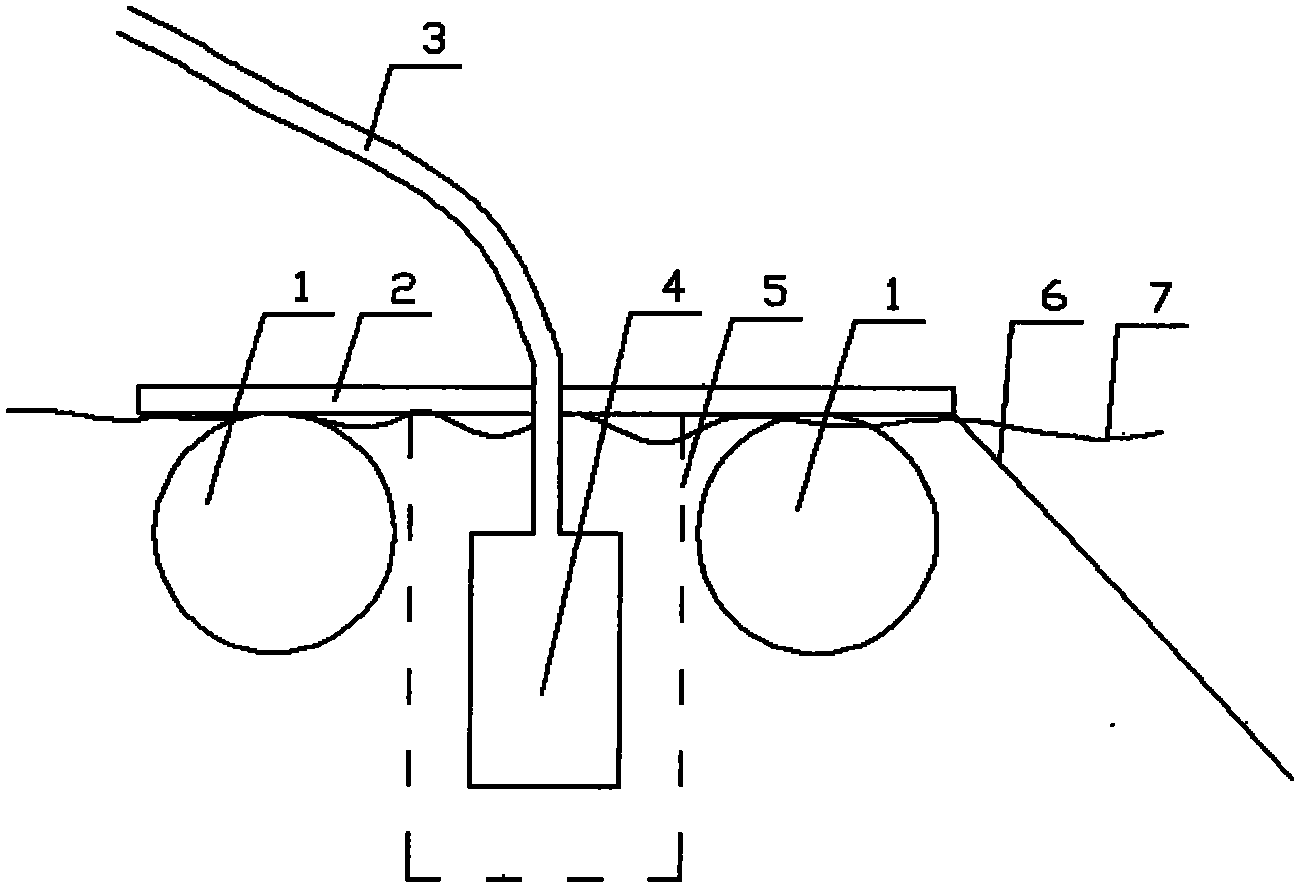
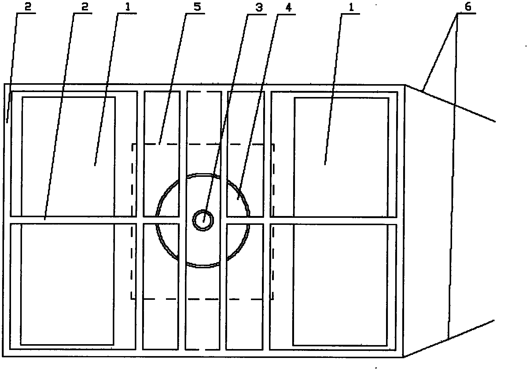
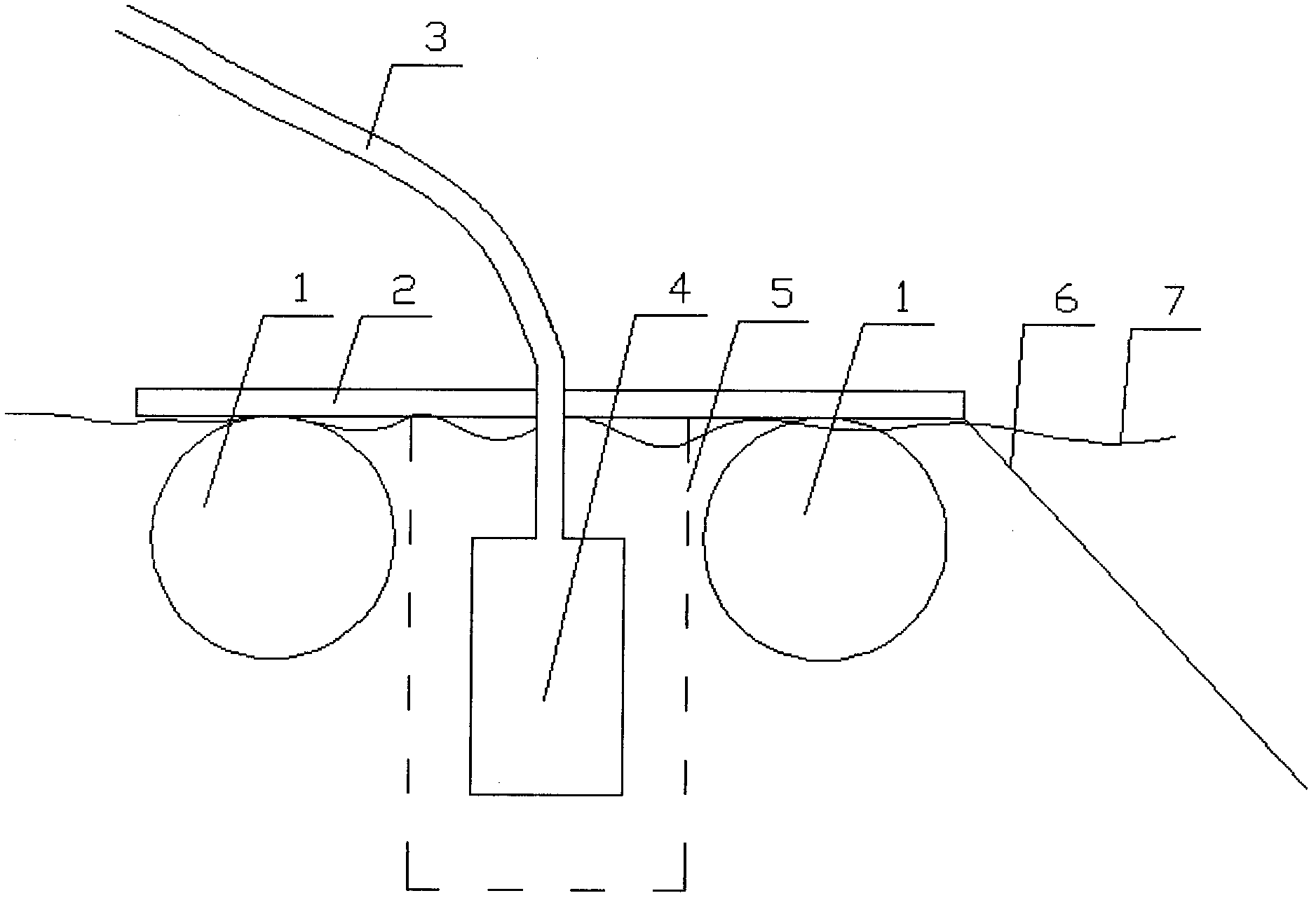
[0017] exist figure 1 Among them, it is a buoy-type water intake device assembled on site by two hollow buoys. The hollow buoy (1) made of two waste oil drums and the fixed bracket (2) are firmly combined to float on the water surface (7) Above, the buoy can be exposed to the water surface or submerged below the water surface; the water intake pump (4) and the filter cover (5) are also fixed below the fixed bracket (2), and are always immersed in water; the lower end of the water intake hose (3) and The water intake pump (4) is connected, and the upper end is connected with the water intake pipeline on the bank, figure 1 Shown is the water intake pump (4) of the upper outlet type, and this patent also includes the water intake pump (4) of the lower outlet water. At this time, the lower end of the water intake hose (3) is connected to the outlet of the underwater intake water pump (4) The upper end of the anchoring sling (6) is fixed on the fixed support (2), and the lower end...


PUM


Abstract

A surface water ground source heat pump central air-conditioner which takes surface water, such as large rivers, rivers, lakes, sea and the like as cold and heat sources uses a fixed water getting device, but the surface water ground source heat pump central air-conditioner can not get water sometime in the places with larger water level fall. The buoy-type water getting device disclosed by the invention uses one or more of hollow buoys to provide enough buoyancy for the whole water getting device; the hollow buoys, a water taking water pump and the filter cover of the water taking water pump are fixed by one bracket, so that the buoys and the whole water getting device form a whole; and the outlet of the water taking water pump is connected with a water getting pipeline on the shore by a hose. The whole water getting device still floats on the water surface and changes along with the height change of the water surface, the water getting water pump is still dipped in water, a water getting hole is still positioned under the water surface for certain height, and water can be gotten at any time. The buoy-type water getting device has the advantages of simple structure and obvious technical and economic advantages and is convenient to construct.

Description

Technical field [0001] The invention relates to a water intake device for a surface water ground source heat pump central air conditioner, in particular to a buoy type water intake device capable of floating on the water surface. Background technique [0002] At present, there are more and more surface water ground source heat pump central air conditioners that use surface water such as rivers, rivers, lakes, and seas as heat sources. This kind of device is a permanent water intake structure. Therefore, it has a wide range of applications. However, this fixed water intake device also has obvious defects. Because the water intake device is fixed, its water intake position cannot be changed regardless of the water level. There may be no access to water. [0003] We had this problem in a five-star hotel project in Hechuan District, Chongqing this year. This project uses the Jialing River water as the cold and heat source to provide sanitary hot water and central air-condition...

Claims


Application Information

Patent Timeline
Patent Type & Authority Applications(China)
IPC IPC(8): E03B3/04
Inventor 斯永生王正渊龙阳
Owner CHONGQING SIKESEN ENVIRONMENTAL PROTECTION TECH
Why Eureka
Try Eureka