Equipment indicator light and installation method thereof

A technology of indicator light and equipment, which is applied in the field of assembly structure of equipment indicator lights, can solve the problems of high labor processing cost, damage to light source 1, and difficulty in process control, so as to reduce costs and processing procedures, the assembly appearance is simple and beautiful, and the process Ease of control

Inactive Publication Date: 2012-06-13
DELTA ELECTRONICS (SHANGHAI) CO LTD +2
View PDF3 Cites 5 Cited by
  • Summary
  • Abstract
  • Description
  • Claims
  • Application Information

AI Technical Summary

Problems solved by technology

from figure 1 It can be seen from the figure that the structure must at least include a light source 1, a fixing device 12, an electric wire 8, a terminal 9, and a heat-shrinkable sleeve 10. The number of components is large, which directly increases the cost of materials.
[0006] 2. Due to the large number of components, the processing procedures are numerous and complicated
[0011] These steps result in higher labor processing costs
[0012] 3. During the process of fixing the light source 1 to the housing 2 via the fixing device 12 and the process of connecting the light source 1 to the wire 8, the light source 1 may be damaged, affecting the life of the light source 1, and the process control is difficult
[0013] 4. Since the light source 1 is fixed on the casing 2, when the casing 2 is subjected to external force, the light source 1 is easily damaged
[0014] 5. The assembly appearance of the whole structure is not beautiful
[0015] 6. In order to meet the requirements of relevant safety regulations, the wire 8 may need to add additional protection, such as adding a sleeve, binding a belt, etc., resulting in an increase in additional material costs

Method used


Image

  • Equipment indicator light and installation method thereof
  • Equipment indicator light and installation method thereof
  • Equipment indicator light and installation method thereof

Examples


Embodiment Construction

[0036] Hereinafter, the present invention will be described in detail with reference to the accompanying drawings.

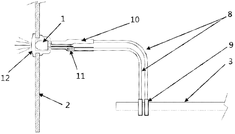
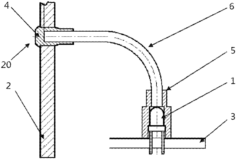
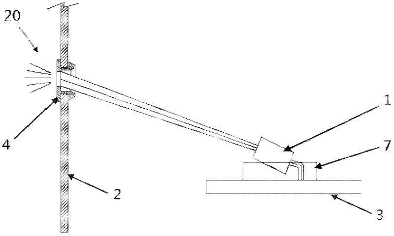
[0037] figure 2 is a schematic diagram of the first embodiment of the device indicator light according to the present invention. Such as figure 2 As shown, the device indicator light of the first embodiment includes: a light source 1, which is directly fixed and electrically connected to the circuit board 3; a display part 20, which is arranged on the casing 2 of the device, and is separated from the light source 1, and the light source 1 emits The light from the light source 1 is emitted to the outside of the device through the display part 20, wherein the light emitted by the light source 1 is guided to the display part 20 of the device through the light guide device 6.

[0038] In this embodiment, the light source 1 is an LED, however, the light source 1 may also be other light emitting devices such as light bulbs. and, according to figure 2 The shown ...


PUM


Abstract

The invention discloses an equipment indicator light and an installation method thereof. The equipment indicator light comprises a light source which is fixed on and electrically connected with a circuit board, and a display component arranged on a casing of equipment. Light from the light source ejects out of the equipment through the display component. The equipment indicator light is few in components, thereby reducing material cost and processing procedures, being easy in processing control, prolonging service life of the light source and enabling assembly of the whole structure to be brief and attractive in appearance.

Description

technical field [0001] The invention relates to an equipment indicator light, and more specifically, relates to an assembly structure of the equipment indicator light and a method for installing the equipment indicator light. Background technique [0002] Usually, one or more indicator lights (for example, power indicator lights) are set on PC computers, instruments, electronic devices and other equipment to display the status of the equipment. In the prior art, the indicator light of the device is through such as figure 1 The structure shown is shown for display. [0003] exist figure 1 Among them, the indicator light of the device includes a light source 1, and the light source 1 (such as an LED or a light bulb) is fixed on the casing 2 of the device by a fixing device 12, and the light source 1 is electrically connected to the circuit board 3 through a wire 8, wherein the pin of the light source 1 Connect with one end of respective electric wire 8 respectively at conne...

Claims


Application Information

Patent Timeline
Patent Type & Authority Applications(China)
IPC IPC(8): F21S8/00F21V19/00F21V8/00F21W111/00
CPCG02B6/0008F21V19/00F21W2111/00F21S8/00G02B6/0006Y10T29/49007
Inventor 荆轮子古武明
Owner DELTA ELECTRONICS (SHANGHAI) CO LTD
Why Eureka
Try Eureka