
Plasma oil-free ignition staged combustion system

A staged combustion and oil-free ignition technology, which is applied in the field of thermal boilers, can solve the problems of poor mixing effect, poor ignition of pulverized coal airflow, and poor combustion stability, and achieve moderate investment and operating costs, high cost performance, and reasonable design.

Active Publication Date: 2012-06-13
SHANGHAI BOILER WORKS
View PDF6 Cites 0 Cited by
  • Summary
  • Abstract
  • Description
  • Claims
  • Application Information

AI Technical Summary

Problems solved by technology

The ignited pulverized coal airflow and the unignited pulverized coal airflow are mixed at the outlet of the cylinder, and the mixing effect is poor, resulting in poor ignition and stable combustion effects of the pulverized coal airflow

Method used


Image

  • Plasma oil-free ignition staged combustion system
  • Plasma oil-free ignition staged combustion system
  • Plasma oil-free ignition staged combustion system

Examples


Embodiment 1

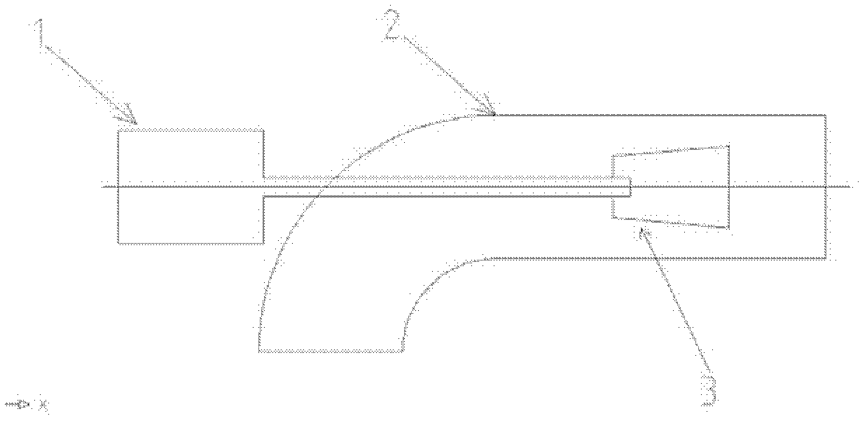
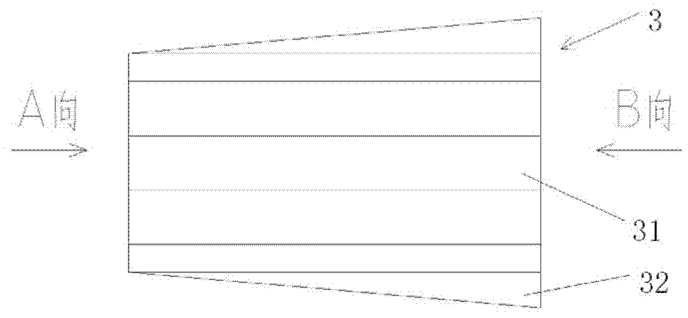
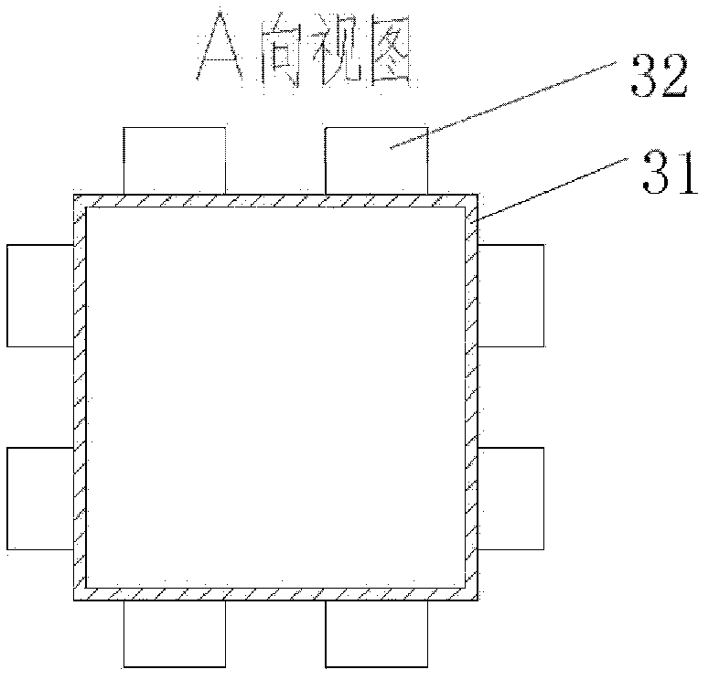
[0030] refer to figure 1 , figure 2 , image 3 , Figure 4 , Figure 5 with Image 6 , a plasma oil-free ignition staged combustion system of the present invention, including a plasma generator 1 and a burner 2. A staged combustion sleeve 3 is arranged inside the burner 2, and the staged combustion sleeve 3 and the burner 2 are arranged coaxially or in parallel. The graded combustion sleeve 3 has a sleeve main body 31. The cross-sectional shape of the sleeve main body 31 is square and equipped with a rectangular expansion cone 32. Two rectangular expansion cones 32 are arranged symmetrically on each side of the sleeve main body 31. The rectangular expansion cones 32 has a taper of 5°, the tip of the cone is at the entrance of the sleeve main body 31, the bottom of the cone is at the exit of the sleeve main body 31, and the sleeve main body 31 and the rectangular expanding cone 32 are integrated.

[0031] When the boiler is ignited, the plasma generator 1 is inserted int...

Embodiment 2

[0034] refer to figure 1 , Figure 7 , Figure 8 , Figure 9 with Figure 10 The difference between this embodiment and Embodiment 1 is that, in this embodiment, the sleeve main body 31 of the staged combustion sleeve 3 adopts a circular shape with a circular expansion cone 32. Four circular expansion cones 32 are evenly arranged on the On the side of the circumference, the cone tip of the expanding cone is at the entrance of the sleeve main body 31 , and the cone bottom of the expanding cone is at the exit of the sleeve main body 31 . The expanding cone 32 has a taper of 5°, and the sleeve main body 31 and the circular expanding cone 32 are integrated.

Embodiment 3

[0036] refer to figure 1 , Figure 11 , Figure 12 , Figure 13 with Figure 14 The difference between this embodiment and Embodiment 1 is that in this embodiment, the sleeve body 31 of the staged combustion sleeve 3 adopts a regular pentagon with a triangular expansion cone 32. Five triangle-shaped expansion cones 32 are evenly arranged On the side of the regular pentagon, the cone tip of the expanding cone is at the entrance of the sleeve main body 31 , and the cone bottom of the expanding cone is at the exit of the sleeve main body 31 . The expansion cone 32 has a taper of 5°, and the sleeve main body 31 and the triangle expansion cone 32 are integrated.


PUM


Abstract

The invention discloses a plasma oil-free ignition staged combustion system, which comprises a plasma generator and a combustor, wherein a staged combustion sleeve is arranged in the combustor and is provided with a sleeve main body; the sleeve main body is arranged coaxially or parallelly with the combustor; and an enlarged taper is arranged on an outer wall surface of the sleeve main body along the circumference. By the technical scheme, because an outlet of the sleeve main body is provided with the enlarged taper, a peripheral length on an end face of the outlet of the staged combustion sleeve is increased, entrainment which is stronger than that generated without the enlarged taper can be formed at the outlet of the sleeve main body, a stable high-temperature flue gas backflow area can be established, the mixing of ignited pulverized coal and unignited pulverized coal inside the combustor is enhanced, the backflow of high-temperature flue gas is strengthened, the ignition success rate is improved, and a stable combustion effect is achieved.

Description

technical field [0001] The invention belongs to the field of thermal boilers, and relates to a boiler combustion system, in particular to a plasma oil-free ignition staged combustion system. Background technique [0002] The traditional way of igniting boilers in power plants is oil gun ignition. When the boiler is ignited, the fuel gun is first lit. After the oil burns in the furnace for a certain period of time, the furnace is heated to the ignition temperature of the pulverized coal flow. At this time, the pulverized coal is blown into the furnace for mixed combustion of oil and coal. When the load of the boiler reaches more than 50% and the pulverized coal flow can burn stably, the fuel oil is gradually cut off to complete the ignition and start-up process of the boiler. In order to save costs and reduce the fuel oil consumption of power plant boilers, many companies at home and abroad have developed a variety of plasma oil-free ignition burners, and have been widely us...

Claims


Application Information

Patent Timeline
Patent Type & Authority Applications(China)
IPC IPC(8): F23D1/00F23Q7/02
Inventor 郑路
Owner SHANGHAI BOILER WORKS
Learn More