Plasma oil-free ignition staged combustor
A technology of oil-free ignition and staged combustion, which is applied to burners, burners burning powder fuel, and combustion methods, etc., can solve the problems of poor adaptability of different coal types, achieve enhanced ignition and stable combustion effects, and improve success rate. cost-effective effect
- Summary
- Abstract
- Description
- Claims
- Application Information
AI Technical Summary
Problems solved by technology
Method used
Image
Examples
Embodiment 1
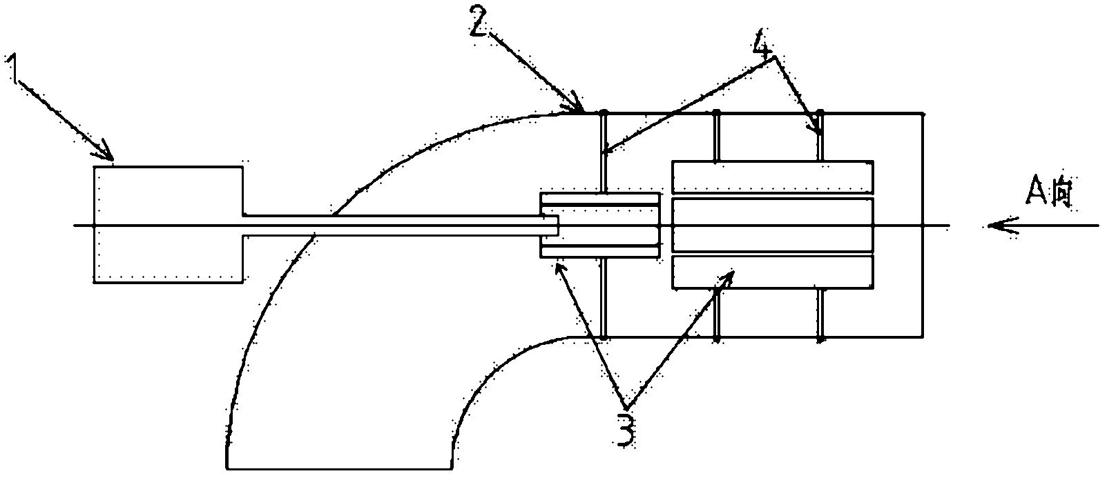
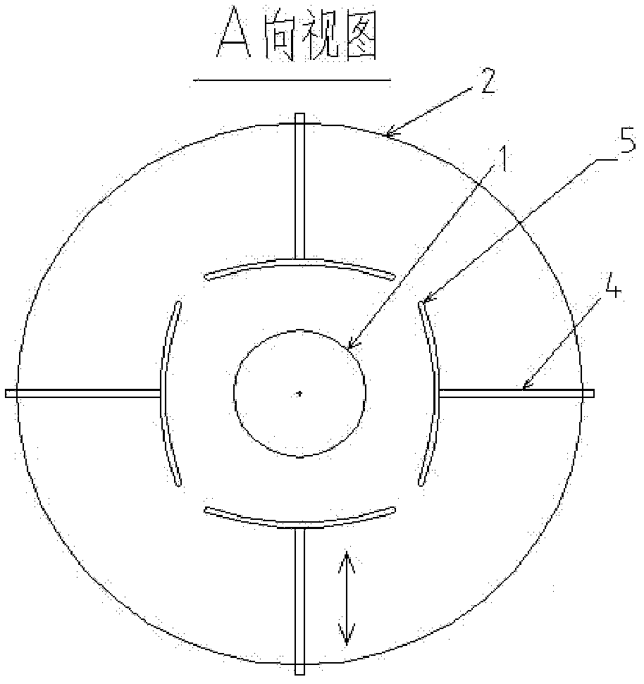
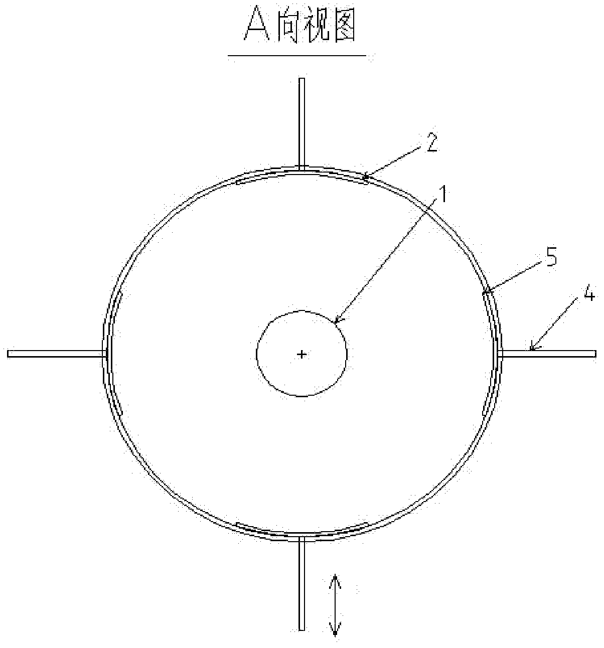
[0027] refer to figure 1 , figure 2 , image 3 and Figure 4 , a plasma oil-free ignition staged burner of the present invention, including a plasma generator 1 and a burner 2. Two sets of guide vane sets 3 are arranged in the burner 2, the guide vane sets 3 include four guide vanes 5, there are gaps between the guide vanes 5, the guide vanes are arc-shaped, the radius of curvature is the same as the radius of curvature of the burner nozzle Similarly, the center of arc of the guide vane 5 is inside the burner, and the guide vane 5 is connected with a movable guide rod 4 . The guide vane set 3 and the combustor 2 are coaxially arranged. like figure 2 As shown, the movable guide rod 4 radially penetrates into the burner 2, and can drive the radial movement of the guide vane 5, and the radial movement is a linear reciprocating movement.
[0028] Before ignition, such as image 3 As shown, the guide vanes 5 are retracted and attached to the inner wall of the burner. When...
Embodiment 2
[0032] refer to figure 1 , Figure 4 , Figure 5 and Image 6 , the difference between this embodiment and Embodiment 1 is that in this embodiment, the guide vane group 3 includes 6 pulverized coal air flow guide vanes 5, the radius of curvature of the guide vanes 5 is the same as that of the burner nozzle, and the guide vanes 5 arc The center of the surface is inside the burner, and each pulverized coal flow guide vane 5 is inserted into the burner 2 in a circular arc reciprocating motion with a certain center point 6 as the center of the circle (the center point 6 is the rotation center of the blade 5). The vane group 3 can divide the pulverized coal flow into two parts (or approximately into two parts). The plasma generator 1 is axially inserted into the space surrounded by the guide vane set 3, ignites the pulverized coal flow entering the space, and forms a new, stable ignition source with higher thermal power at the outlet of the guide vane set 3 end , using this ign...
Embodiment 3
[0036] refer to Figure 7 , Figure 8 and Figure 9 , the difference between this embodiment and Embodiment 1 is that in this embodiment, the guide vane group 3 includes 5 pulverized coal flow guide vanes 5, the radius of curvature of the guide vanes 5 is the same as that of the burner nozzle, and the guide vanes 5 arc The center of the circle of the surface is outside the burner, the movable guide rod 4 pushes the guide vane group 3 into the burner axially from the burner, and the guide vane group 3 can also be axially withdrawn from the burner through the movable guide rod 4, that is, the guide vane 3 from axial ( Figure 9 Insert or withdraw the burner in the vertical direction of the paper. The vane group 3 can divide the pulverized coal flow into two parts (or approximately into two parts). The plasma generator 1 is axially inserted into the space surrounded by the blade group 3, ignites the pulverized coal flow entering the space, and forms a new, stable, and higher ...
PUM
 Abstract
Description
Claims
Application Information
 - R&D
- Intellectual Property
- Life Sciences
- Materials
- Tech Scout
- Unparalleled Data Quality
- Higher Quality Content
- 60% Fewer Hallucinations
Browse by: Latest US Patents, China's latest patents, Technical Efficacy Thesaurus, Application Domain, Technology Topic, Popular Technical Reports.
© 2025 PatSnap. All rights reserved.Legal|Privacy policy|Modern Slavery Act Transparency Statement|Sitemap|About US| Contact US: help@patsnap.com


