
Trapped vortex type micro-turbine engine combustion chamber

A gas turbine and engine technology, applied in the direction of combustion chamber, continuous combustion chamber, combustion method, etc., can solve the problems of insufficient combustion of fuel, short combustion residence time, increased heat transfer loss, etc., to reduce wall temperature and temperature gradient , Improve combustion stability and combustion efficiency, and increase the effect of residence time

Active Publication Date: 2018-04-13
SICHUAN AEROSPACE ZHONGTIAN POWER EQUIP CO LTD
View PDF5 Cites 7 Cited by
  • Summary
  • Abstract
  • Description
  • Claims
  • Application Information

AI Technical Summary

Problems solved by technology

As one of the key technologies of MTE, the combustion chamber has a large surface-to-volume ratio due to its miniaturization (millimeters to centimeters) and a greatly increased heat transfer loss.
Burning residence time is short, resulting in incomplete combustion of fuel

Method used


Image

  • Trapped vortex type micro-turbine engine combustion chamber
  • Trapped vortex type micro-turbine engine combustion chamber
  • Trapped vortex type micro-turbine engine combustion chamber

Examples


Embodiment

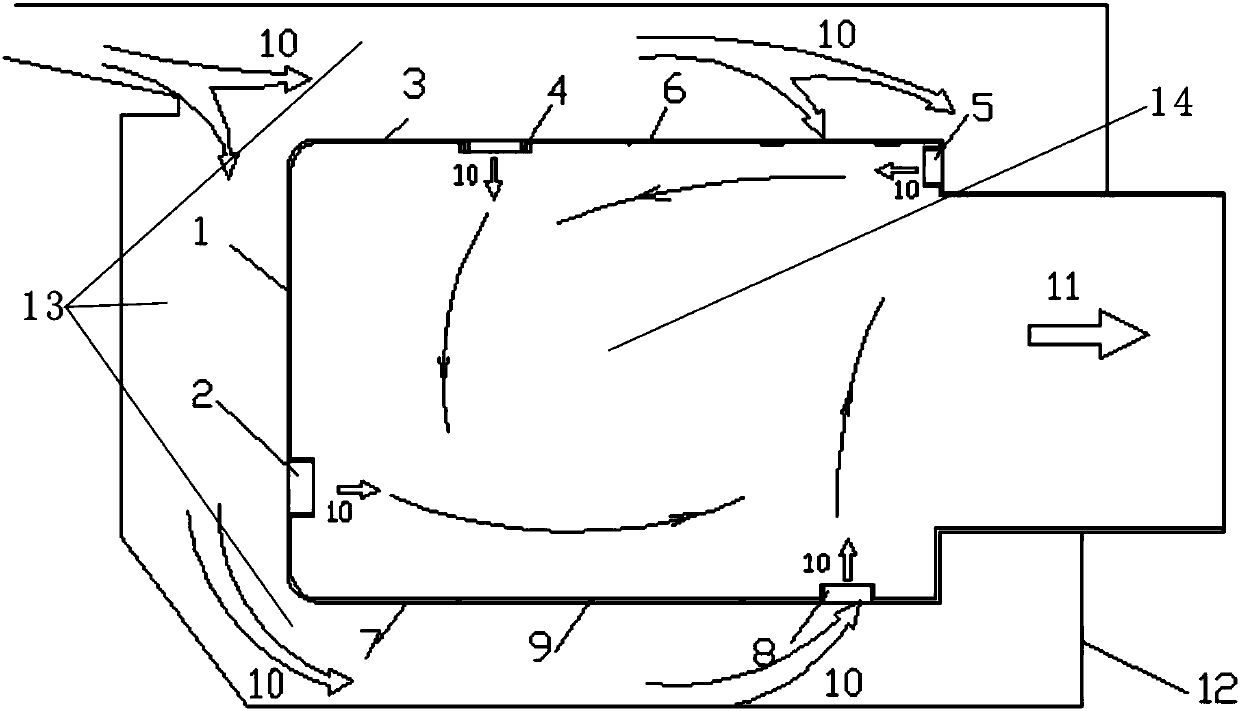
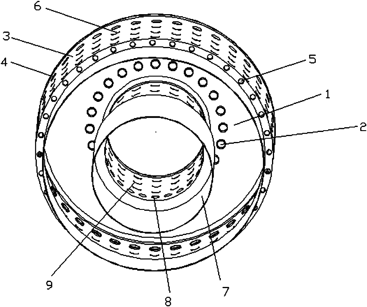
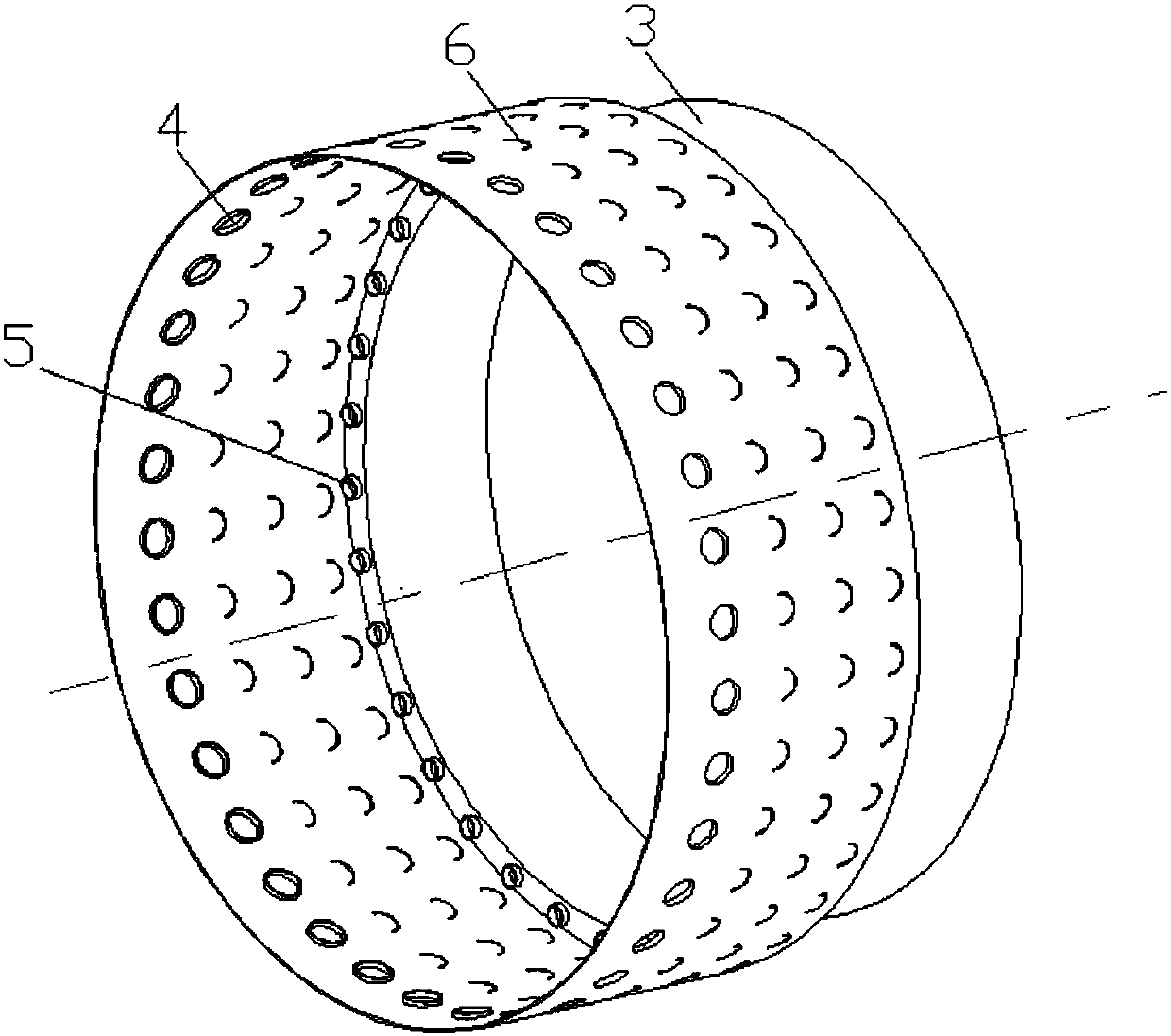
[0027] like Figure 1 to Figure 5 As shown, a combustion chamber of a vortex type micro gas turbine engine comprises a flame tube and a casing 12, and the flame tube includes a flame tube outer wall 3, a flame tube front wall 1 and a flame tube inner wall 7; the flame tube is close to the flame tube front wall 1 One end is the main combustion area at the head of the flame tube, the main combustion area at the head of the flame tube adopts a sudden expansion structure, and the main combustion area at the head of the flame tube is a vortex structure. The flame tube outer wall 3 is sealed and fixedly connected with the flame tube front wall 1, the flame tube inner wall 7 is located inside the flame tube outer wall 3, and the flame tube inner wall 7 is sealed and fixedly connected with the flame tube front wall 1. Both the outer wall 3 of the flame tube and the inner wall 7 of the flame tube of the present invention adopt a variable section design. The outer wall 3 of the flame t...


PUM


Abstract

The invention discloses a trapped vortex type micro-turbine engine combustion chamber comprising a flame tube and an engine casing. The flame tube comprises a flame tube outer wall, a flame tube frontwall and a flame tube inner wall, wherein the flame tube outer wall, the flame tube front wall and the flame tube inner wall are sealed to form a flame tube airflow cavity A, and an annular cavity Bis formed between the flame tube and the engine casing. The flame tube outer wall is provided with a second jet flow hole. The end, far away from the flame tube front wall, of the flame tube outer wall is provided with a third jet flow hole. The flame tube front wall is provided with a first jet flow hole. A fourth jet flow hole is formed in the flame tube inner wall. A first group of cooling holes are formed in the flame tube outer wall. The flame tube inner wall is provided with a second group of cooling holes. By the adoption of the trapped vortex type micro-turbine engine combustion chamber, a center strong backflow region enables the staying time of air flow in the combustion chamber to be prolonged, the peripheral low-speed-zone area of the backflow region is widened, so that spreading of flame is facilitated, and therefore the combustion in the head region is stable.

Description

technical field [0001] The invention relates to the field of micro gas turbine engine combustors, in particular to a stationary vortex micro gas turbine engine combustor. Background technique [0002] Micro-turbine en-gine (MTE) has the advantages of light weight, high power and high thrust-to-weight ratio. For small and micro unmanned aerial vehicles, they will play an increasingly important role in the future, such as air reconnaissance, target training, electronic jamming, communication relay, environmental monitoring, nuclear radiation sampling and ground attack. With the demand for the development of unmanned aerial vehicles in recent years, micro-turbine engines have also been greatly developed accordingly. The United States is the first country in the world to carry out research on small and micro turbine engine technology, and it is also the country with the most models and the most advanced technologies. In 1960, Williams International Corporation of the United St...

Claims


Application Information

Patent Timeline
Patent Type & Authority Applications(China)
IPC IPC(8): F23R3/50
CPCF23R3/50
Inventor 王丹丹陈溯周君辉黄超然
Owner SICHUAN AEROSPACE ZHONGTIAN POWER EQUIP CO LTD
Learn More