
Device and method for detecting drilling tool well head magnetic flux

A detection device, a technology of magnetic flux, applied in the direction of material magnetic variables, etc., can solve the problem of ineffective detection of changes in the cross-sectional area of ​​drilling tools, and achieve the effect of a simple detection process

Active Publication Date: 2014-08-20
CHINA NAT PETROLEUM CORP CHUANQING DRILLING ENG CO LTD
View PDF5 Cites 1 Cited by
  • Summary
  • Abstract
  • Description
  • Claims
  • Application Information

AI Technical Summary

Problems solved by technology

[0007] During the drilling process, drilling tool cracks, holes, and punctures are the main methods for judging waste. The above technical solutions can only be detected when the drilling tool has cracks, holes, and punctures.
When there are no cracks, holes and punctures, wear is the main method for grading the quality of drill tools, and wear is not the strength of the magnetic flux leakage detection represented by the above-mentioned patent documents, and it cannot effectively detect the damage caused by wear or corrosion of drill tools. cross-sectional area change

Method used


Image

  • Device and method for detecting drilling tool well head magnetic flux
  • Device and method for detecting drilling tool well head magnetic flux
  • Device and method for detecting drilling tool well head magnetic flux

Examples


Embodiment 1

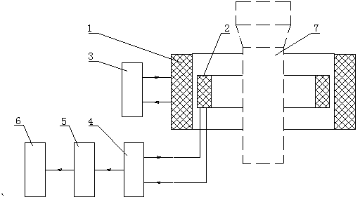
[0038] Refer to the attached figure 1 , The invention discloses a drilling tool wellhead magnetic flux detection device, which includes a current pulse generator, a primary coil, a secondary coil, an instrument amplifier circuit, a filter circuit, an A / D conversion and a host computer. The primary coil is on the outside and provides a pulse magnetic field for the drilling tool, and the pulse current generator provides pulse current for the primary coil. The secondary coil is installed inside the primary coil, and the wires of the secondary coil are connected with the instrument amplifying circuit. The instrument amplifier circuit, filter and A / D converter form a signal conditioning circuit, the secondary coil wire is connected to the instrument amplifier circuit, the instrument amplifier circuit is connected to the filter circuit, the filter circuit is connected to the A / D converter, and the A / D The converter is connected with the host computer.

[0039] At the same time, m...

Embodiment 2

[0045] The drilling tool wellhead magnetic flux detection method provided by the present invention is characterized in that the steps include:

[0046] Step 1: Hold the automatic slip card under the drill string collar, and then hoist it in the turntable;

[0047] Step 2: Install the detection device on the automatic slips;

[0048] Step 3: Provide pulse current to the primary coil through the current pulse generator of the detection device;

[0049] Step 4: Use the secondary coil to obtain the wear and corrosion of the inner and outer surfaces of the drilling tool; when the primary coil is energized, an instantaneous current will be generated in the secondary coil to obtain an instantaneous voltage. The current intensity and voltage generated by electromagnetic induction depend on The magnetic permeability and cross-sectional area of ​​the drilling tool material, the severe wear or corrosion of the internal and external surfaces of the drilling tool will cause the cross-sect...

Embodiment 3

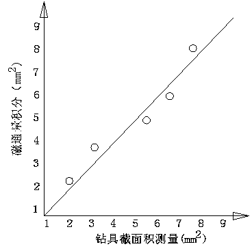
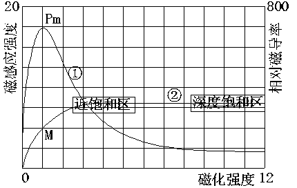
[0058] The best implementation of the detection method is to control the pulse current of the primary coil to control the magnetic field strength, so as to control the magnetic permeability of the drilling tool to the maximum value. Specifically: the control of sensor parameters. The magnetic flux is equal to the product of the magnetic permeability and the magnetic field strength. The cross-sectional area of ​​the drilling tool changes due to wear and corrosion, and the magnetic field strength that can be sensed changes. Therefore, an electromagnetic sensor, that is, a secondary coil, can be used to measure the change in cross-sectional area. In order to enable the secondary coil to sense the change of the magnetic flux of the drilling tool, the primary coil is required to provide a sufficiently strong magnetic field. Usually, the stronger the magnetization, the larger the volume of the primary coil. When the primary coil applies a magnetic field to the drilling tool, only wh...


PUM


Abstract

The invention discloses a device for detecting a drilling tool well head magnetic flux, relating to the technical field of designing and producing oil drilling tool well head nondestructive testers. The device comprises a current pulser, a primary coil, a secondary coil, an instrumentation amplifying circuit, a filter circuit, an A / D converter and a host computer, wherein the current pulser is connected with the primary coil, the secondary coil is arranged in the primary coil, a drilling tool to be detected is arranged in the secondary coil, the guide wire of the secondary coil is connected with the instrumentation amplifying circuit, the instrumentation amplifying circuit is connected with the filter circuit, the filter circuit is connected with the A / D converter, and the A / D converter is connected with the host computer. Simultaneously the invention also discloses a method for detecting the device. According to the invention, the sectional area change caused by wearing or corrosion can be effectively detected when the drilling tool has no crack, hole and diapirism, and the invention has a direct and visual effect on the quality grading relying on the thickness change of the drilling tool rod body wall.

Description

technical field [0001] The invention relates to the technical field of design and manufacture of oil drilling tool wellhead non-destructive testing instruments, in particular to a drilling tool wellhead magnetic flux detection device and method. Background technique [0002] The inspection of drilling tools usually adopts methods such as magnetic flux leakage, ultrasonic wave, eddy current and naked eye observation, focusing on cracks, holes, and punctures. These methods are not the most effective methods for the detection of inner and outer surface wear of drilling tools. [0003] In the existing automatic non-destructive testing technology for drilling tools in field stations, automatic magnetic flux leakage detection has become a detection method with a higher degree of automation. Strong magnetization magnetic flux leakage detection method and device. [0004] This patent adopts a single through-type magnetizing coil to carry out local single axial super-strong magn...

Claims


Application Information

Patent Timeline
Patent Type & Authority Patents(China)
IPC IPC(8): G01N27/83
Inventor 谭刚强王豫李丽何莎曹历杰许斌
Owner CHINA NAT PETROLEUM CORP CHUANQING DRILLING ENG CO LTD
Learn More