Panoramic imaging lens

A panoramic imaging lens and panoramic technology, applied in the field of panoramic lenses, can solve the problems of poor real-time performance and low reliability, and achieve the effects of simplifying structure, improving transmittance, and suppressing stray light.

Inactive Publication Date: 2012-06-13
FUDAN UNIV
View PDF4 Cites 27 Cited by
  • Summary
  • Abstract
  • Description
  • Claims
  • Application Information

AI Technical Summary

Problems solved by technology

[0010] In view of the disadvantages of poor real-time performance and low reliability of the sys

Method used


Image

  • Panoramic imaging lens
  • Panoramic imaging lens
  • Panoramic imaging lens

Examples


Embodiment Construction

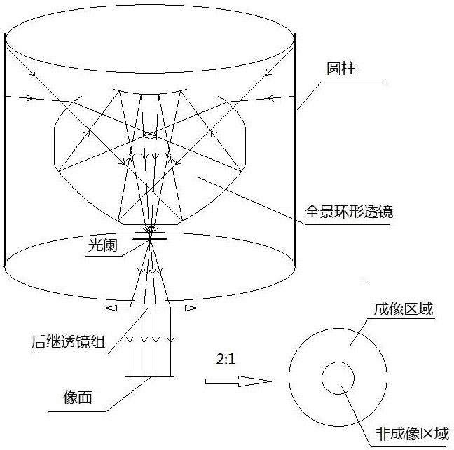
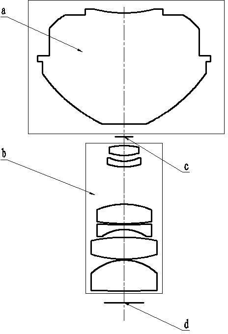
[0055] Such as figure 2 As shown, the main components of the panoramic lens of the present invention include a panoramic annular lens a, a subsequent lens group b, a diaphragm c, and an image plane d (where the CCD / CMOS detector is located).

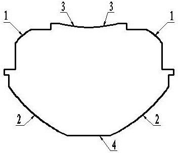
[0056] Such as image 3 As shown, the panoramic annular lens a is composed of a transparent medium, two refraction surfaces and two reflection surfaces, and is rotationally symmetrical around the central optical axis. The material used for the transparent medium is PMMA engineering plastic.

[0057] Such as image 3 As shown, 1 is the first refracting surface, and its surface shape is an outwardly protruding annular rotational axisymmetric free-form surface; 2 is the first reflecting surface, and its surface shape is an outwardly protruding annular rotational axisymmetric free-form surface; 3 is The second reflection surface is a concave spherical surface, and 4 is the second refraction surface, and the surface shape is a plane. Wher...


PUM


Abstract

The invention belongs to the technical field of optical devices, and particularly discloses a panoramic imaging lens, comprising a panoramic annular lens, a subsequent lens system, a diaphragm and an image surface which are positioned on the same optical axis. The panoramic annular lens is made of a transparent medium in the shape of a convex polyhedron rotationally symmetric around the center optical axis, and the convex polyhedron consists of four refracting surfaces and two reflecting surfaces; the subsequent lens system consists of a series of spherical lenses made of different transparent media; the diaphragm is positioned between the panoramic annular lens and the subsequent lens system; and the image surface is positioned at the bottom end of a system. The panoramic imaging lens has the advantages of high resolution, low radial distortion, capability of avoiding distortion after an image is restored, and the like. In addition, the panoramic imaging lens is simple in structure, easy in processing and low in cost. The panoramic imaging lens is mounted at the front of a camera, and a simple panoramic image can be shot by the camera. Besides, the panoramic imaging lens can be applied to fields of pipeline detection, observation by the aid of a medical endoscope, video monitoring and the like.

Description

technical field [0001] The invention belongs to the technical field of optical devices, and in particular relates to a panoramic imaging lens, in particular to a panoramic lens with long focal length and high resolution, which can realize 360° panoramic imaging in real time. Background technique [0002] With the development of digital image processing technology and CCD / COMS detector technology, higher requirements and challenges are put forward for traditional optical imaging systems. With a large field of view, traditional imaging techniques cannot meet its requirements. Panoramic imaging technology is a new imaging technology developed along with binary optical technology, free-form surface processing technology, digital image correction technology, and large-area staring imaging CCD / COMS detector technology. Compared with traditional imaging technology, its most notable feature is that its field of view is a circular field of view, which can realize 360° surround-view ...

Claims


Application Information

Patent Timeline
IPC IPC(8): G02B13/06G02B17/08G03B37/00
Inventor 王军华徐敏
Owner FUDAN UNIV
Why Eureka
Try Eureka