Visual three-dimensional stereoscopic imaging method and operation microscope utilizing same

An imaging method and three-dimensional technology, which can be used in microscopes, surgery, applications, etc., can solve the problems of cumbersome imaging methods, high cost, and distortion of three-dimensional images, and achieve the effects of convenient observation and recording, convenient diagnosis and cost saving.

Inactive Publication Date: 2012-06-13
SUZHOU KANGJIE MEDICAL
View PDF6 Cites 32 Cited by
  • Summary
  • Abstract
  • Description
  • Claims
  • Application Information

AI Technical Summary

Problems solved by technology

[0002] The existing three-dimensional stereoscopic imaging method and the three-dimensional image of the surgical microscope are based on the dual optical path design of the surgical microscope. A digital camera is installed at the end of each optical path to collect images during the operation, simulate the imaging process of the retina of both eyes, and then process the paired images to form Stereoscopic images, through the stereoscopic mirror to obtain a three-dimensional effect, this imaging method is more cumbersome, and this kind of product structure is more complicated, the cost is expensive, and at the same time, the requirements for image acquisition and synthesis technology are high, and the three-dimensional image synthesized by computer is distorted, so it cannot be Completely displaying the reality of images may cause deviations in medical diagnosis; at present, most stereoscopic film productions are still in the state of computer three-dimensional virtual rendering, and real shooting is due to the synchronous focus, synchronous zoom, and synchronous angle adjustment of the two camera pan-tilts. It is very difficult for several people to work synchronously at the same time, and it is very expensive to synthesize three-dimensional images through computers in the later stage

Method used


Image

  • Visual three-dimensional stereoscopic imaging method and operation microscope utilizing same
  • Visual three-dimensional stereoscopic imaging method and operation microscope utilizing same
  • Visual three-dimensional stereoscopic imaging method and operation microscope utilizing same

Examples


Embodiment Construction

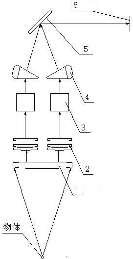
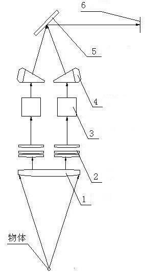
[0012] like figure 1 A visible three-dimensional imaging method is shown. The light reflected by the object is firstly refracted by the objective lens 1, and the refracted light is divided into two paths by two symmetrical angles and passed through the left beam path imaging mirror 2 and the right beam path imaging mirror 2 respectively. Refraction, the two refracted rays pass through the left dichroic prism 3 and the right dichroic prism 3, respectively, and then the two refracted rays pass through the left-turning prism 4 and the right-turning prism 4 respectively, focus twice at 45°, and converge to the same reflector 5, then transmitted to the display through the CCD 6.

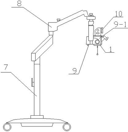
[0013] like figure 2 A surgical microscope using a visible three-dimensional imaging method is shown, including a mobile bracket 7 on which a rotating pendant 8 is installed, and a three-dimensional microscope 9 is installed on the rotating pendant 8 .

[0014] The three-dimensional microscope includes...


PUM


Abstract

The invention relates to a visual three-dimensional stereoscopic imaging method and an operation microscope utilizing the method. The three-dimensional stereoscopic imaging method comprises the following steps: light reflected by an object passes through an object lens for refraction, the refracted light is divided into two paths which pass through a left light splitting path imaging mirror and a right light splitting path imaging mirror respectively for refraction, and the two paths of refracted light pass through a left image rotation prism and a right image rotation prism respectively to focus on a same reflective mirror and then are transmits to a video display unit through a video. The operation microscope comprises a mobile support which is installed with a rotation head mast, and the head mast is provided with a three-dimensional microscope. After employing the three-dimensional stereoscopic imaging method, there is no need to carry out shooting through two cameras and then carry out later computer synthesis, and cost is saved. Through the operation microscope prepared by employing the method, observation and record can be carried out conveniently, an effect of distortion is not generated, and accurate diagnosis is facilitated.

Description

technical field [0001] The invention relates to an optical imaging method and a three-dimensional stereoscopic operating microscope applying the method in the medical operation industry. Background technique [0002] The existing three-dimensional stereoscopic imaging method and the three-dimensional image of the surgical microscope are based on the dual optical path design of the surgical microscope. A digital camera is installed at the end of each optical path to collect images during the operation, simulate the imaging process of the retina of both eyes, and then process the paired images to form Stereoscopic images, through the stereoscopic mirror to obtain a three-dimensional effect, this imaging method is more cumbersome, and this kind of product structure is more complicated, the cost is expensive, and at the same time, the requirements for image acquisition and synthesis technology are high, and the three-dimensional image synthesized by computer is distorted, so it c...

Claims


Application Information

Patent Timeline
IPC IPC(8): G02B21/22G02B27/22A61B19/00A61B90/00
Inventor 朱永林
Owner SUZHOU KANGJIE MEDICAL
Why Eureka
Try Eureka