
Assembly structure of insulating rolling bearing

A technology of rolling bearing and assembly structure, applied in the direction of electromechanical devices, electric components, manufacturing of motor generators, etc., can solve the problem of unsuitable insulating bearing sleeve structure, and achieve the effect of saving radial space and protecting electric corrosion

Inactive Publication Date: 2012-06-13
SEC ELECTRIC MACHINERY
View PDF3 Cites 3 Cited by
  • Summary
  • Abstract
  • Description
  • Claims
  • Application Information

AI Technical Summary

Problems solved by technology

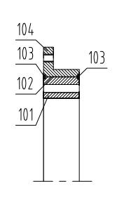
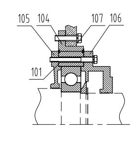
According to the strength and reliability requirements, a certain distance should be ensured between the polyimide film layer 102 of the insulating bearing sleeve and the installation hole of the sleeve 101, and the axial mating surface of the polyimide film layer 102, the bearing sleeve 104 and the end cover 107 There should be a certain distance between them. Therefore, when the inner and outer covers of the bearing and the bearing remain unchanged, the radial size of the insulated bearing sleeve must be larger than the size of the non-insulated bearing sleeve. In some occasions where the radial installation size of the bearing assembly is limited, The existing insulating bearing sleeve structure is not applicable, and it is necessary to adopt an insulating bearing structure that can reliably block the shaft current without increasing the radial space

Method used


Image

  • Assembly structure of insulating rolling bearing
  • Assembly structure of insulating rolling bearing
  • Assembly structure of insulating rolling bearing

Examples


Embodiment Construction

[0018] The specific embodiments of the present invention will be further described below in conjunction with the accompanying drawings.

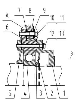
[0019] Such as image 3 As shown, the assembly structure of the insulating rolling bearing of the present invention mainly includes a bearing outer cover 1, a shaft retaining ring 2, an oil throwing pan 3, a rolling bearing 4, a bearing inner cover 5, an insulating bearing sleeve 6, an insulating washer 7, and an insulating tube 8 , Insulation washer 9, Belleville spring 10, hex bolt 11, spring washer 12 and hex bolt 13.

[0020] The rolling bearing 4 is sleeved on the shaft, and the two ends of the inner ring of the rolling bearing 4 are axially positioned by the shaft shoulder and the oil throwing pan 3 respectively, and the two ends of the outer ring of the rolling bearing 4 are positioned by the bearing inner cover 5 and the bearing outer cover 1 respectively. The oil throwing pan 3 is positioned by the inner ring of the rolling bearing...


PUM


Abstract

The invention provides an assembly structure of an insulating rolling bearing. An insulating bearing sleeve of the assembly structure consists of a bearing sleeve and a sleeve ring, wherein an insulating washer is arranged between radial matching surfaces of the bearing sleeve and the sleeve ring, a polyimide film layer is padded between axial matching surfaces of the bearing sleeve and the sleeve ring, an annular groove is formed at a joint seam of the other radial end faces of the bearing sleeve and the sleeve ring, and epoxy resin strips are filled in the groove; and the insulating bearing sleeve is combined with the an end cover through a belleville spring and hex bolts, an insulating washer is arranged between the radial matching surfaces of the insulating bearing sleeve and the end cover, an insulating pipe is sleeved at an axial matched part of the hex bolts and the end cover, and an insulating washer is arranged between the radial matching surfaces of the belleville spring and the end cover. By adoption of the insulating bearing sleeve, and insulating devices are arranged between the insulating bearing sleeve and a radial abutted surface of the end cover, and between a fastening piece of the insulating bearing sleeve and the end cover and an abutted surface of the end cover, the assembly structure disclosed by the invention can reliably block a shaft current path between a bearing assembly and the end cover, and then protect the bearing from electro-corrosion. The assembly structure disclosed by the invention saves the radial space, and is particularly suitable for occasions on which the radial space for bearing assembly is limited.

Description

technical field [0001] The invention relates to an insulating bearing assembly structure, in particular to an insulating bearing assembly structure using rolling bearings. Background technique [0002] The shaft current generated during the operation of the motor forms a loop through the shaft, bearing, end cover, and frame, which causes electrical corrosion to the bearing, seriously damages the working surface of the bearing, and then affects the operating performance of the motor. In order to block the shaft current from passing through the bearing, it is necessary to cut off its circuit. The effective measure is to use insulating bearings or equivalent insulating structures. Due to the high price and limited supply of insulating bearings, it is an economical and effective measure to adopt an equivalent insulating structure. [0003] It is a common measure to use insulating bearing sleeves to block the axial current path between the bearing assembly and the end cover. The...

Claims


Application Information

Patent Timeline
IPC IPC(8): H02K15/14
Inventor 冯嫦杰赵文辉
Owner SEC ELECTRIC MACHINERY
Learn More