Parallel turbine flow sensor

A turbine flow and sensor technology, applied in the field of sensors, can solve the problems of measurement, axial positioning and radial anti-rotation difficulties, and the impossibility of processing and assembly, and achieve the effect of reducing radial space

Pending Publication Date: 2019-07-23
KAIFENG INSTR
View PDF0 Cites 1 Cited by
  • Summary
  • Abstract
  • Description
  • Claims
  • Application Information

AI Technical Summary

Problems solved by technology

However, with the development of the nuclear industry in recent years, the use environment of nuclear reactor hydraulic simulation experiments cannot be measured by conventional turbines.
The operating environment of the nuclear reactor hydraulic simulation experiment is that hundreds of square or circular outer diameter tubes are arranged in a large container to form a tube bundle. The gap between each tube is 2 mm, and the wall thickness is relatively thin. The method is arranged according to the conventional turbine structure, and only a solution is found on the cramped side wall; and the movement of the traditional turbine flowmeter is installed from both ends of the casing and fixed by the compression ring. There are not too many restrictions on installation, the general length is not long, the length of the DN50 caliber instrument is 150 mm, and the processing and assembly are relatively easy
However, the pipes used in nuclear reactor hydraulic simulation experiments are 500 mm to 5 meters long, and the internal shoulders, grooves and other structures are not allowed to be changed. A small inner diameter is used to arrange the turbine flowmeter, which will bring great difficulties to axial positioning and radial anti-rotation

Method used


Image

  • Parallel turbine flow sensor
  • Parallel turbine flow sensor
  • Parallel turbine flow sensor

Examples


Embodiment Construction

[0024] The present invention will be further described below in conjunction with the accompanying drawings and specific embodiments.

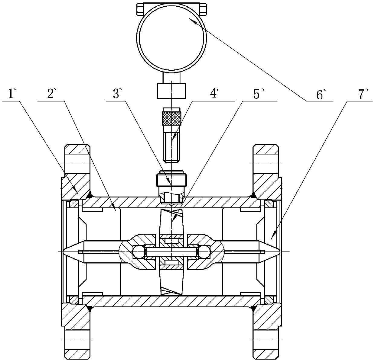
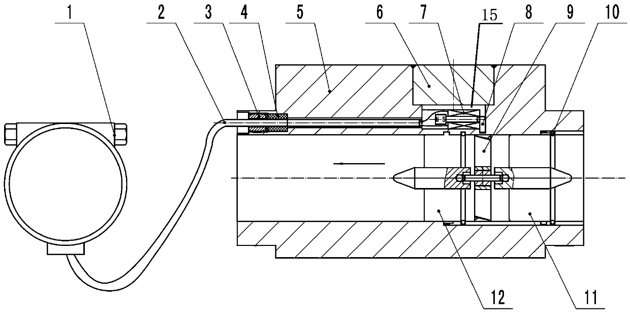
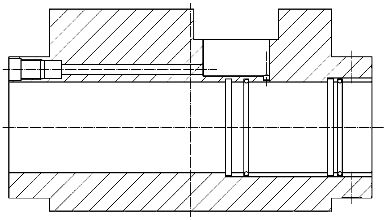
[0025] Such as Figure 2-8 As shown, the parallel turbine flow sensor of the present invention includes a housing 5, an impeller assembly 9 axially installed in the medium flow chamber of the housing, and front and rear flow guides 12, respectively installed at both ends of the impeller assembly 9. 11. Two front card slots 13 and rear card slots 14 are axially processed on the inner wall of the medium flow chamber at one end of the housing, each pair of front card slots and rear card slots do not overlap, and each pair of front card slots Both between and between the rear slots are symmetrical with respect to the axis of the housing; the outer edges of the two vanes on the same plane in the front deflector 12 are all processed with protrusions for being snapped into the front slots 13 ; The outer edges of the two blades on the same plane in th...


PUM


Abstract

The present invention discloses a parallel turbine flow sensor, including a casing, an impeller assembly, and front and rear flow guiding members. The front guiding member, a front guiding member pressing member, the impeller assembly, and the rear guiding member, and the rear guide member pressing member are sequentially installed from one end of the housing. A detection groove is disposed on anouter side wall of the casing, and a signal detector in which an iron core is parallel to a rotating shaft of the impeller assembly is disposed in the detection groove. A signal output end of the signal detector is connected to a wire, and the wire is connected to a signal input end of a signal amplifier. A sealing block is mounted in the detection groove outside the signal detector. An expanded core perpendicular to the iron core of the signal detector is disposed between the other end of the signal detector relative to the other end of an outlet and an inner wall of the detection groove. Theexpanded core corresponds to the position of the impeller assembly, and the upper end of the expanded core and the right end of the iron core of the signal detector are fitted. A fastening seal assembly is disposed at the outer end of the through hole through which the wire passes.

Description

technical field [0001] The invention belongs to a sensor in the field of liquid and gas flow measurement, and in particular relates to a turbine flow sensor whose signal detector is parallel to the direction of the impeller rotation axis and whose core is fixed from one end of the shell to be suitable for nuclear reactor hydraulic simulation experiments. Background technique [0002] Turbine flow sensor is a flow measurement instrument, which is widely used in process control, flow measurement, storage and transfer, and trade measurement. Its working principle is that when the fluid passes through, it pushes the impeller with helix angle to rotate, and the impeller made of magnetic permeable material periodically changes the magnetic flux of the coil of the external signal detector of the sensor, and generates an electric pulse signal in the coil, which is passed through the amplifier Amplify processing, output square wave signal to display or computer, calculate instantaneo...

Claims


Application Information

Patent Timeline
Patent Type & Authority Applications(China)
IPC IPC(8): G01F1/28G01F1/56
CPCG01F1/28G01F1/56
Inventor 张红琴林洋靳文哲房相如马园吴志军张金艳李晓芳刘长礼张建勇王波赵育萱付宁超杨振宇李国选李金聚沈磊
Owner KAIFENG INSTR
Why Eureka
Try Eureka