High-precision zero drift compensation circuit for analog multiplier

A technology of analog multiplier and compensation circuit, which is applied in the direction of reliability improvement and modification, which can solve the problems of large influence of analog multiplier, inconsistent input bias current, and limited suppression effect, so as to improve accuracy and reduce bias The effect of simple current and circuit structure

Inactive Publication Date: 2012-06-13
NAVAL UNIV OF ENG PLA
View PDF5 Cites 11 Cited by
  • Summary
  • Abstract
  • Description
  • Claims
  • Application Information

AI Technical Summary

Problems solved by technology

[0004] Using the circuit compensation method to suppress the zero drift of the analog multiplier is mainly to take corresponding measures to compensate the circuit parameters at the input terminal and the zero adjustment terminal. Generally, the differential input is used at the input terminal of the analog multiplier. When the single-ended input mode is used, it is To reduce the influence of the bias current at the input terminal, it is necessary to ensure that the equivalent impedance from the two input terminals to the ground is consistent, but the bias current at the two input terminals is not strictly consistent, so the suppression effect of this method is limited
In addition, the bias voltage at the output terminal of the analog multiplier is compensated by adding a fixed voltage to the zero-adjustment terminal, but in traditional applications, the resistance from the zero-adjustment terminal to ground is selected to be relatively large, resulting in the bias current of the zero-adjustment terminal affecting the analog multiplier. greater impact

Method used


Image

  • High-precision zero drift compensation circuit for analog multiplier
  • High-precision zero drift compensation circuit for analog multiplier
  • High-precision zero drift compensation circuit for analog multiplier

Examples


Embodiment Construction

[0020] The present invention will be further described below in conjunction with the accompanying drawings and specific embodiments.

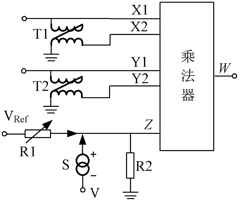
[0021] Such as figure 1 As shown, the high-precision analog multiplier zero-drift compensation circuit includes an analog multiplier, the first input end of the analog multiplier is connected to a first unbalanced-balanced transmission line transformer T1, and the second input end is connected to a second unbalanced- Balanced transmission line transformer T2. Wherein, the first unbalanced-balanced transmission line transformer T1 and the second unbalanced-balanced transmission line transformer T2 are both composed of a ring core and a transmission line wound on the ring core, and the ring core is a high-frequency magnetic ring.

[0022] The zeroing end of the analog multiplier is respectively connected to a grounding resistor R2, a temperature sensor S and a zeroing resistor R1, wherein the temperature sensor S is connected to the working powe...


PUM


Abstract

The invention discloses a high-precision zero drift compensation circuit for an analog multiplier. The influence of zero drift on the analog multiplier is compensated. The high-precision zero drift compensation circuit comprises the analog multiplier, a transmission line transformer, a reference power supply, a zeroing resistor, a grounding resistor and a temperature sensor, wherein the transmission line transformer is connected to the input end of the analog multiplier, and is used for reducing the influence of biasing current at the input end on the analog multiplier; and fixed voltage is applied to the zeroing end of the multiplier through the reference power supply, the zeroing resistor and the grounding resistor in a voltage share manner to compensate the biasing voltage at the output end. The grounding resistor with a low resistance value is used for reducing the influence of the biasing current at the zeroing end on the analog multiplier; and compensation voltage of which the temperature excursion size is equal to that of the multiplier and the direction is opposite to the direction of the multiplier is formed at the zeroing end of the multiplier through the temperature sensor and the grounding resistor, so that the influence of the temperature excursion on the analog multiplier is reduced effectively. The high-precision zero drift compensation circuit has a simple structure; and suppression to the zero drift of the analog multiplier is improved by an order of magnitude.

Description

technical field [0001] The invention relates to an analog multiplier, in particular to a high-precision analog multiplier zero-drift compensation circuit, which belongs to the field of circuit design and signal processing. Background technique [0002] In the field of signal processing, analog multipliers and low-pass filters are usually used to extract signal correlation. When the signal is weakly correlated, the zero drift of the analog multiplier will affect the extraction accuracy of the correlation. Therefore, effective measures must be taken to suppress the zero drift of the analog multiplier. [0003] The zero drift of the analog multiplier is related to the input bias current, input bias voltage, output bias voltage and temperature drift. At present, two methods are mainly used to suppress the zero drift of the multiplier, that is, chopper zero stabilization and circuit compensation. The chopper zero stabilization method has higher adjustment accuracy, but it will ...

Claims


Application Information

Patent Timeline
Patent Type & Authority Applications(China)
IPC IPC(8): H03K19/003
Inventor 唐健李文禄肖欢赵治华李毅何方敏潘启军张磊陶涛张向明
Owner NAVAL UNIV OF ENG PLA
Why Eureka
Try Eureka