
Contact sensor for lawns

A contact sensor, sensor unit technology, applied in the direction of instruments, lawn mowers, cutters, etc., can solve the problems of dust pollution, easy aging and wear, and inductive devices and sensors are difficult to work in a long-term environment.

Inactive Publication Date: 2014-07-09
林小冬
View PDF5 Cites 2 Cited by
  • Summary
  • Abstract
  • Description
  • Claims
  • Application Information

AI Technical Summary

Problems solved by technology

Because when the lawn mowing robot mows on the grass, its working environment and working conditions are very complicated and harsh, and ordinary sensors cannot do it for a long time
When the lawn mowing robot is working on the grass, its motion route and direction will change frequently, resulting in frequent changes in the contact state between the sensing device installed on the body and the grass, such as the contact position and contact direction; At the same time, the large amount of broken grass and grass juice generated during the mowing process and the dust raised from the ground will continue to pollute until the sensor device is damaged; the numerous debris on the grass and the undulating ground will also collide and even damage the sensor from time to time. Sensing device; a large amount of water in the grass and outdoor cloudy weather and even rainy days will affect the normal use and service life of the sensing device; Also very susceptible to aging and wear
The superposition of the above factors makes it difficult for general sensing devices and sensors to withstand such a harsh working environment for a long time
At the same time, in order to avoid affecting the normal walking and working of the lawn mowing robot on the grass, the sensing device used to identify the grass and the length of the grass cannot produce excessive walking resistance to the lawn mowing robot, and the angular and overly large structure cannot meet such requirements.
All of this is plaguing the development and application of lawn mowing robots

Method used


Image

  • Contact sensor for lawns
  • Contact sensor for lawns
  • Contact sensor for lawns

Examples


Embodiment Construction

[0032] The present invention will be described in further detail below in conjunction with the accompanying drawings.

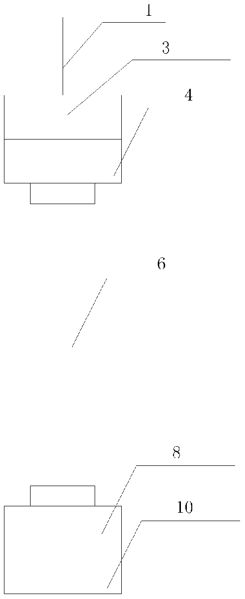
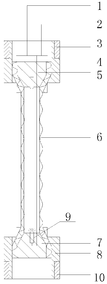
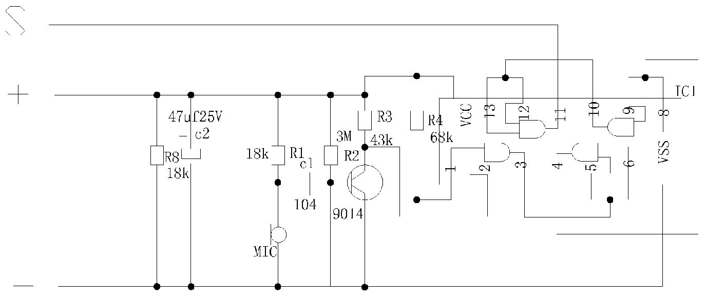
[0033] The technical solution of the present invention is to use an acoustic-electric transducer to receive the acoustic signal generated when it touches the grass. The acoustic-electric transducer is installed in a closed elastic casing, and the contact end of the casing has a certain height from the ground. . When the contact end of the sensor housing touches the grass, the acoustic-electric converter receives the sound wave generated when the object touches and converts it into weak electric energy, and then outputs a level signal that meets the requirements of the digital signal after being amplified by the amplifier circuit. This is used to perceive the grass and the length of the grass in contact.

[0034] Such as figure 1 , 2 As shown, the brush contact sensor of the present invention includes an upper housing and a lower housing communicated by an ...


PUM


Abstract

A contact sensor for lawns comprises an upper casing and a lower casing connected by a middle connecting tube (6), an amplifying circuit (2) is arranged in the upper casing, one end of a general wiring harness (1) is connected with the amplifying circuit (2), the other end of the general wiring harness (1) extends out of the upper casing, an upper plug (5) is arranged at the lower end of the upper casing, a lower plug (7) is arranged at the upper end of the lower casing, a sensor unit is arranged in the lower casing or arranged in the upper casing and the lower casing separately. The contact sensor for lawns mounted on the chassis of a mowing robot is used for identifying the lawns and the length of the lawns, and can adapt to the working environment and conditions without affecting the normal walking of the mowing robot on the lawns.

Description

technical field [0001] The invention relates to a matching device for a mowing robot, in particular to a brush contact sensor. In particular, it refers to the sensing device installed on the chassis of the mowing robot to sense the grass and the length of the grass. Background technique [0002] Most of the existing lawn mowing robots cannot actively identify the grass on the ground and the change in length before and after the grass is cut. As a result, the lawn mowing robot itself cannot directly identify the working area and range of activities to be mowed. At the same time, it is also impossible to select an energy-saving and efficient walking path and working mode by identifying the change in length of the grass before and after being cut. [0003] In order to solve the above-mentioned problems, most of the known lawn mowing robots are solved by adding some auxiliary facilities and equipment. The most commonly used method is to install signal generators and signal line...

Claims


Application Information

Patent Timeline
IPC IPC(8): G01B21/02A01D34/00A01D101/00
CPCA01D34/008G01B21/02
Inventor 林小冬
Owner 林小冬
Learn More