
Tray type automatic seeding machine for seeding raising

A technology of a seeder and a seeding mechanism, applied in the field of agricultural machinery, can solve the problems of missing seeds and inaccurate planting, and achieve the effects of avoiding seed damage, improving the emergence rate, and solving inaccurate planting.

Inactive Publication Date: 2012-06-20
崔永军
View PDF5 Cites 2 Cited by
  • Summary
  • Abstract
  • Description
  • Claims
  • Application Information

AI Technical Summary

Problems solved by technology

[0005] In this scheme, by setting the seed chamber on the upper left side of the rotating seed shaft, the seeds will automatically fall into the seed holes on the rotating seed shaft through the seed taking port during the rotation of the rotating seeds; The elastic material in close contact with the rotating seed shaft avoids the damage of seeds caused by the extrusion of hard objects on the one hand, and improves the seed emergence rate; on the other hand, it solves the problem of seeds missing from the seed bin; A row of seed outlets are covered on the bottom of the outer circumference of the bin, so that the seeds can only be accurately sown into the holes of the tray from the seed outlets at the lower end of the sowing cover, solving the problem of inaccurate sowing of traditional seedling seeders. 100% seeding rate

Method used


Image

  • Tray type automatic seeding machine for seeding raising
  • Tray type automatic seeding machine for seeding raising
  • Tray type automatic seeding machine for seeding raising

Examples


Embodiment Construction

[0020] The patent will be further described in detail below in conjunction with the drawings.

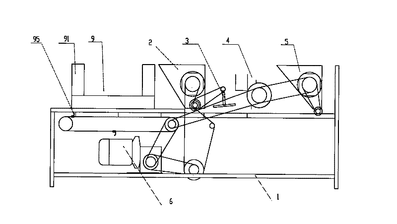
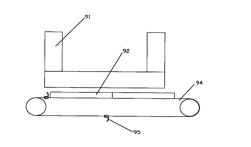
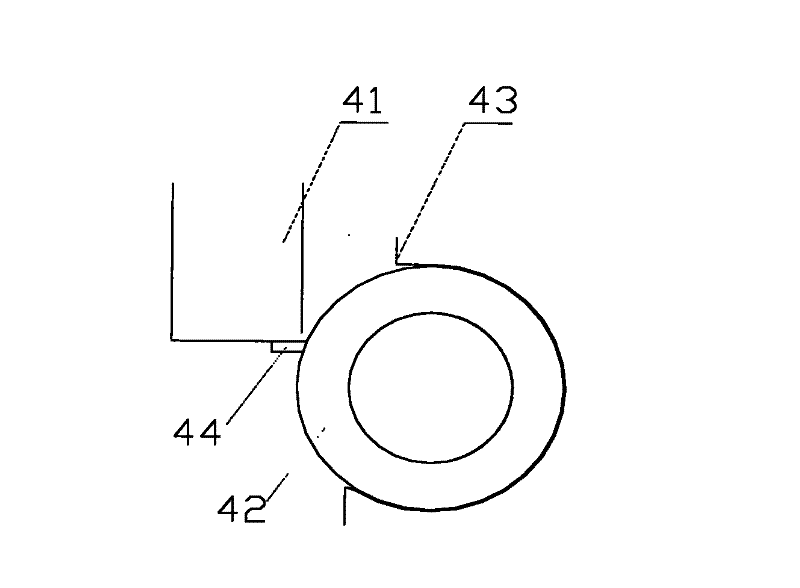
[0021] Such as Figure 1-Figure 4 As shown, the tray seedling automatic planter of the present invention includes a frame 1, on which a tray feeding mechanism 9, a substrate loading mechanism 2, a cavitation mechanism 3, and a rotating seeding mechanism 4 are arranged in sequence. The tray feeding mechanism 9, The substrate mounting mechanism 2, the cavitation mechanism 3, and the rotary seeding mechanism 4 are driven by the same power source. In this embodiment, the power source is a motor 6, which is driven by a chain driven by a reducer. The tray feeding mechanism 9 includes a tray box 91 and a tray feeding chain 94. The tray feeding chain 94 is provided with a push plate 95; during planting, the tray 92 is placed in the tray box 91 and stacked, and the lowest tray 92 is placed on the tray feeding chain. 94 on; the motor 6 drives the reel chain 94 to move, and the push plate 95 on ...


PUM


Abstract

The invention discloses a tray type automatic seeding machine for seeding raising, comprising a machine frame, wherein a tray feeding mechanism, a matrix loading mechanism, an indenting mechanism and a rotary seeding mechanism are sequentially arranged on the machine frame. The tray feeding mechanism, the matrix loading mechanism, the indenting mechanism and the rotary seeding mechanism are driven by a same power source. The rotary seeding mechanism comprises a seed bin, a rotary seed shaft and a seeding cover. The seed bin is arranged on the upper left side of the rotary seed shaft, and a nonmetal elastic material in close contact with the rotary seed shaft is arranged at the lower end of a seed taking opening of the seed bin. A plurality of axially annular grooves are arranged on the circumferential surface of the rotary seed shaft, and a plurality of seed holes are arranged at the bottoms of the annular grooves. The seeding cover is covered over an outer circumferential surface of the rotary seed shaft deviated from the seed bin, and a row of seed outlets corresponding to the seed holes on the rotary seed shaft are arranged at the lower end of the seeding cover. By adopting the scheme of the invention, the seed germination rate is improved on one hand, and on the other hand the problem of seed leaking from the seed bin is solved and the seeding rate is up to 100%.

Description

Technical field [0001] The invention relates to the field of agricultural machinery, in particular to a tray-type automatic seedling planter. Background technique [0002] Tray-type soilless seedlings are widely used due to the fast seedling raising speed, high seedling density, and high survival rate. However, the tray-type soilless seedlings are mostly manual or semi-mechanical chemical operations due to the large density and small diameter of the tray seedlings. Characteristic, it is easy to produce uneven seeding, missed seeding or various phenomena during artificial seeding, which affects the quality of seedlings, and the work intensity is high, the seeding efficiency is low, and it cannot meet the requirements of large-scale seedlings. The Chinese invention patent with the announcement number CN201307993Y discloses a floating seedling automatic loading planter. The frame of the planter is sequentially installed with a floating plate conveyor, a substrate loading mechanism a...

Claims


Application Information

Patent Timeline
IPC IPC(8): A01C7/18A01C7/20A01G9/08A01G13/02
Inventor 崔永军
Owner 崔永军
Learn More