User-defined button control device of full automatic false tooth engraving and milling machine

A kind of engraving and milling machine, fully automatic technology, applied in medical science, dentistry, dental prosthesis, etc., can solve the problems of restricting equipment operability and emergency treatment ability, and achieve the effect of improving maintenance efficiency and safety

Active Publication Date: 2015-01-21
SHINVA MEDICAL INSTR CO LTD
View PDF7 Cites 0 Cited by
  • Summary
  • Abstract
  • Description
  • Claims
  • Application Information

AI Technical Summary

Problems solved by technology

This seriously limits the maneuverability of the equipment and the ability to deal with emergencies

Method used


Image

  • User-defined button control device of full automatic false tooth engraving and milling machine

Examples


Embodiment 1

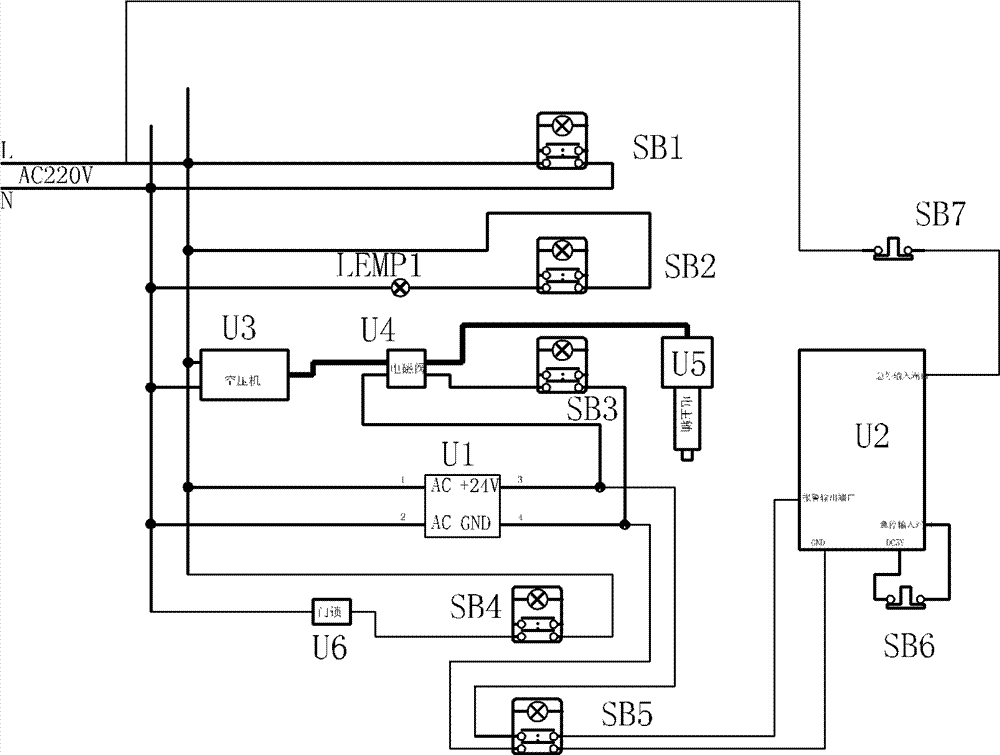
[0025] like figure 1 As shown, the 220V main circuit input is connected to the air compressor U3, the output of the air compressor U3 is connected to the electric spindle U5 of the automatic denture engraving and milling machine through the solenoid valve U4, and the 220V main circuit input is connected to the parallel power indicator circuit and lighting The control circuit and the electric spindle solenoid valve control circuit, the output end of the solenoid valve control circuit is connected to the control end of the solenoid valve U4.

[0026] The power indicator circuit includes an indicator light, which is connected between the two ends of the 220V main circuit input; the indicator light is an LED light-emitting tube, and is also a unified button indicator light, which is used as the status display of the total power supply at the front of the device.

[0027] The lighting control circuit includes the button indicator light SB2 and the lighting light LEMP1, the button i...

Embodiment 2

[0032] On the basis of Embodiment 1, the output end of the control board U2 is provided with an emergency stop button SB7. The alarm input end of the control board U2 is provided with a button indicator light SB5 connected to the power supply chip U2 to provide a manual alarm signal, and the button of the button indicator light SB5 is connected in series with the indicator light. Provides an alarm display and displays the alarm status.

Embodiment 3

[0034] On the basis of Embodiment 1, the 220V main circuit input is provided with a door lock control circuit connected in parallel with the power indicating circuit. The door lock control circuit includes a door lock U6 and a button indicator light SB4, and the door lock and the button indicator light SB4 are connected in series in the 220V main circuit. Between the two ends of the input, the button and the indicator light of the button indicator light SB4 are connected in series. Control the switch of the door lock U6, and display the status of the door lock U6, providing more status information.

[0035] The door lock U6 and the control board U2 among the present invention are common prior art, and its setting and use are grasped by those skilled in the art.

[0036] Working process and principle:

[0037] The specific implementation method of the function of the button indicator light is as follows: 1. The lighting circuit is connected in series with the two main circuit ...


PUM


Abstract

A user-defined button control device of a full automatic false tooth engraving and milling machine belongs to the field of control devices of false tooth equipment and comprises a 220V main circuit input. The user-defined button control device is characterized in that the 220V main circuit input is connected with a power indication circuit, an illuminating lamp control circuit and an electric spindle electromagnetic valve control circuit which are connected in parallel, an output end of the electromagnetic valve control circuit is connected with a control end of an electromagnetic valve, a power chip is connected with a control board, and a scram button is disposed at a scram input end of the control board. A plurality of button indication lamps and scram switches are disposed on an equipment operation panel of the engraving and milling machine, furthermore, the equipment operation panel of the engraving and milling machine has a user-defined function, and as each button indication lamp simultaneously provides a switch function and a state indication function, the integral user-defined button control device is optimized by the aid of an original control system of the full automatic false tooth engraving and milling machine and the control board card. The user-defined button control device is simple and reliable, functions of button indication lamps of a user-defined operation panel are realized, functions of the button indication lamps can be reasonably combined, and accordingly the user-defined button control device meets needs of every user.

Description

technical field [0001] The invention belongs to the technical field of denture processing in the oral restoration industry, and relates to a control device for a fully automatic denture engraving and milling machine, in particular to a custom button control device for a fully automatic denture engraving and milling machine. Background technique [0002] At this stage, the mainstream automatic denture engraving and milling machines are mainly controlled by computers, and the operability of the operation panel carried by the equipment itself has limitations-simple setting of a few buttons or display lights. The function of a limited number of button indicator lights cannot be used indefinitely, and the function of each button indicator light can be determined by the user himself, so as to realize a reasonable combination of button indicator light functions and realize the most convenient implementation plan for each customer. This seriously limits the operability of the equipm...

Claims


Application Information

Patent Timeline
Patent Type & Authority Patents(China)
IPC IPC(8): A61C13/34
Inventor 王冬冬李慧福蒲业飞王永波颉宏勇荣先军
Owner SHINVA MEDICAL INSTR CO LTD
Why Eureka
Try Eureka