Welding lift frame

A technology of lifting frame and supporting member, which is applied in the field of lifting frame

Inactive Publication Date: 2012-06-20
江苏利柏特股份有限公司
View PDF4 Cites 9 Cited by
  • Summary
  • Abstract
  • Description
  • Claims
  • Application Information

AI Technical Summary

Problems solved by technology

[0002]At present, during the welding process of workpieces (mainly steel pipes), the steel pipes are placed on a support frame with a fixed height. Because the steel pipes are very heavy, it is very difficult for workers to operate during welding. Convenient, you can neither adjust the height of the support frame according to your own needs, nor rotate the steel pipe at any time according to the needs of the welding operation
In addition, the material of the welding support frame currently used is mostly carbon steel, and the direct contact between the carbon steel material and the workpiece is likely to cause corrosion of the raw material, affecting the service life of the raw material and product quality

Method used


Image

  • Welding lift frame
  • Welding lift frame
  • Welding lift frame

Examples


Embodiment 1

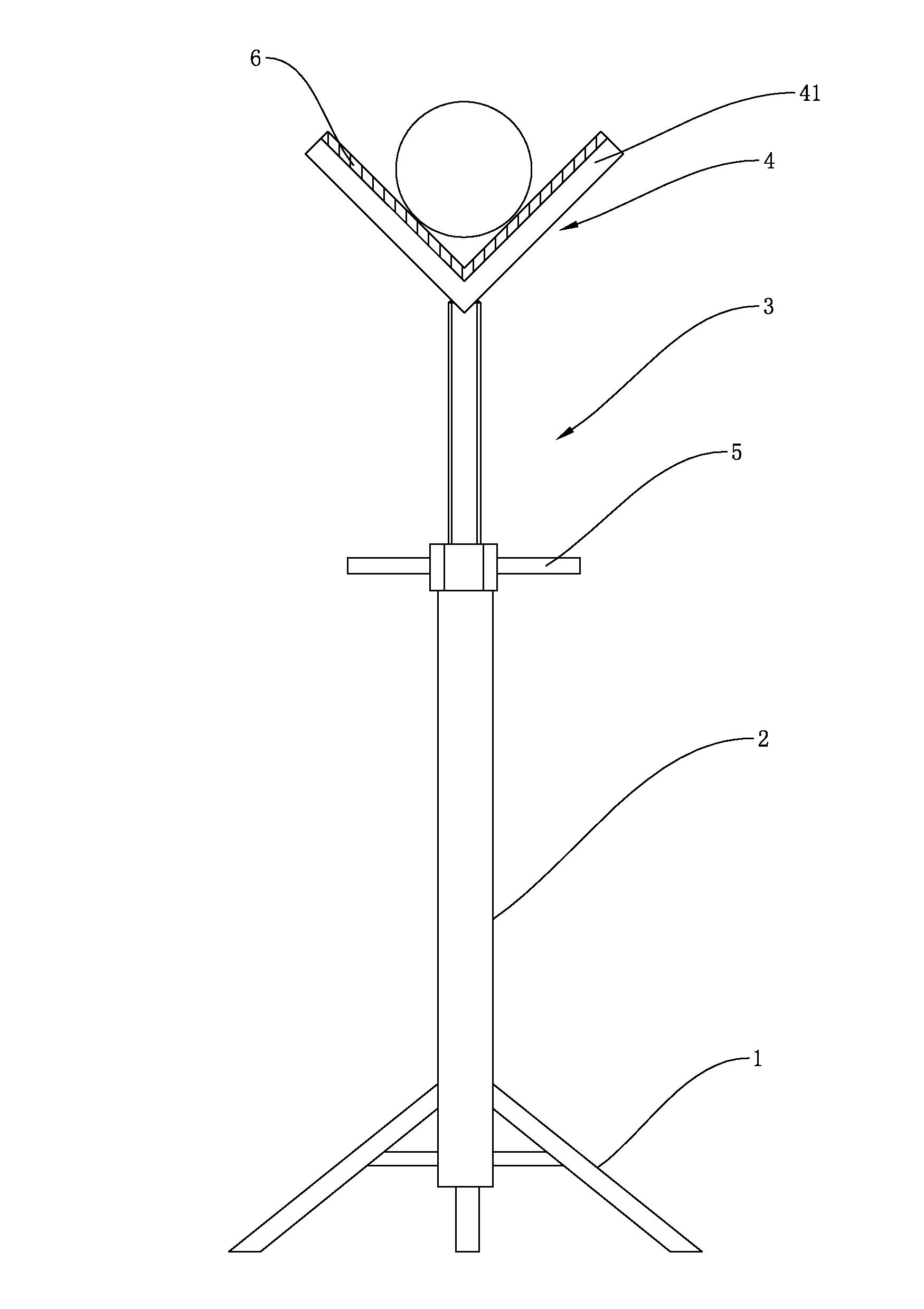
[0028] Such as figure 1 and Figure 4 As shown, a welding lifting frame includes a bracket 1, a sleeve 2 is installed on the upper end of the bracket 1, and a lead screw of a lead screw nut mechanism 3 is sleeved in the sleeve 2, and the lead screw of the lead screw nut mechanism 3 A support 4 is installed on the upper end of the bar. The support described in this embodiment is selected as a V-shaped support 4. The support surface of the support 4 is covered with a protective layer 6 to prevent the workpiece from being corroded by the support 4. In this implementation In the example, the protective layer 6 is a tetrafluoroethylene plate, the nut of the screw nut mechanism 3 is installed on the sleeve 2, and a wrench 5 is installed on the nut of the screw nut mechanism 3 . When the worker is welding, he can turn the wrench 5 to adjust the support member 4 to a suitable height as needed.

Embodiment 2

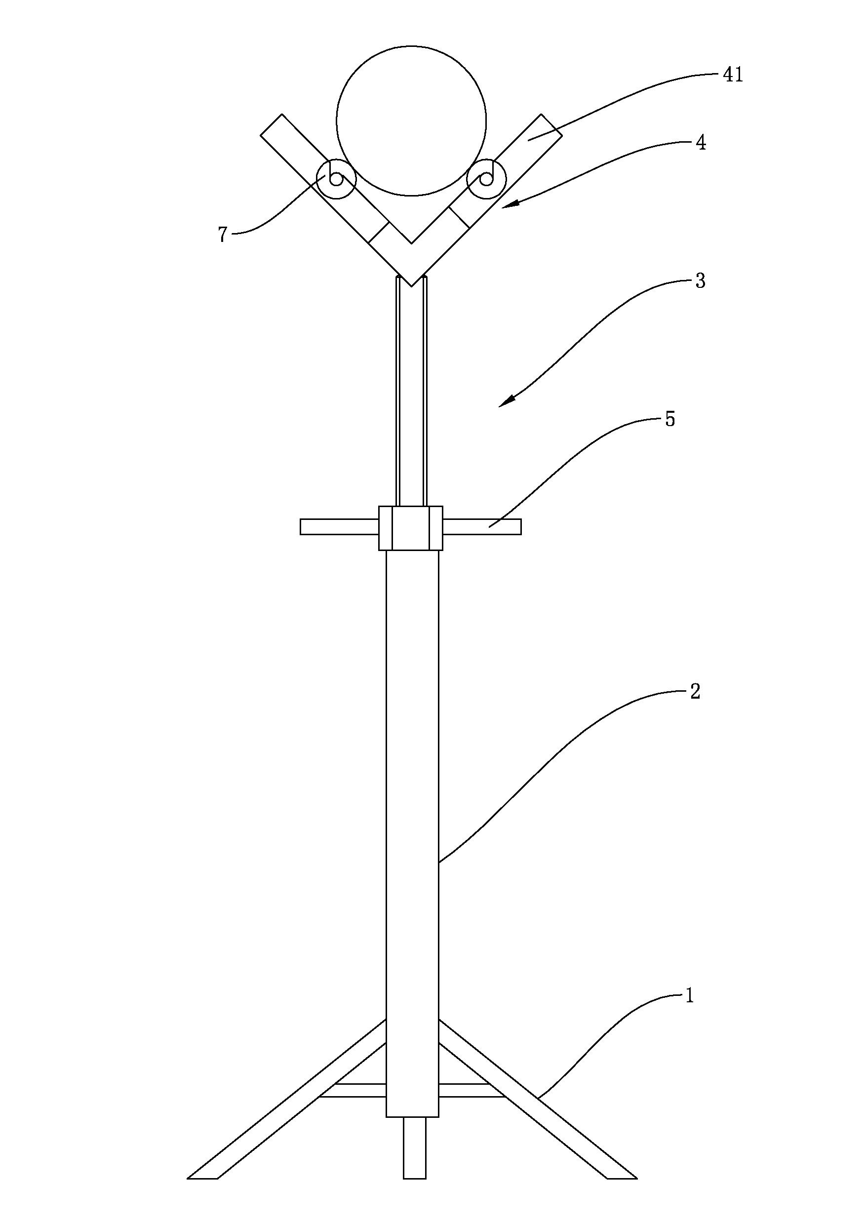
[0030] Such as figure 2 As shown, a welding lifting frame includes a bracket 1, a sleeve 2 is installed on the upper end of the bracket 1, a lead screw of a lead screw nut mechanism 3 is sleeved in the sleeve 2, and a nut of the lead screw nut mechanism 3 Installed on sleeve 2. A wrench 5 is installed on the nut of the lead screw nut mechanism 3, a V-shaped support 4 is installed on the upper end of the lead screw of the lead screw nut mechanism 3, and a V-shaped support 4 is installed on the two support plate parts 41 of the support 4 respectively. The support roller 7 is provided with at least one set of angularly symmetrical installation grooves on the support plate portion 41. In this embodiment, a set of angularly symmetrical installation grooves is provided, and the support roller shaft of the support roller 7 is inserted into the installation groove Inside. Determine the size of the diameter of the support roller 7 according to the pipe diameter of the workpiece to b...

Embodiment 3

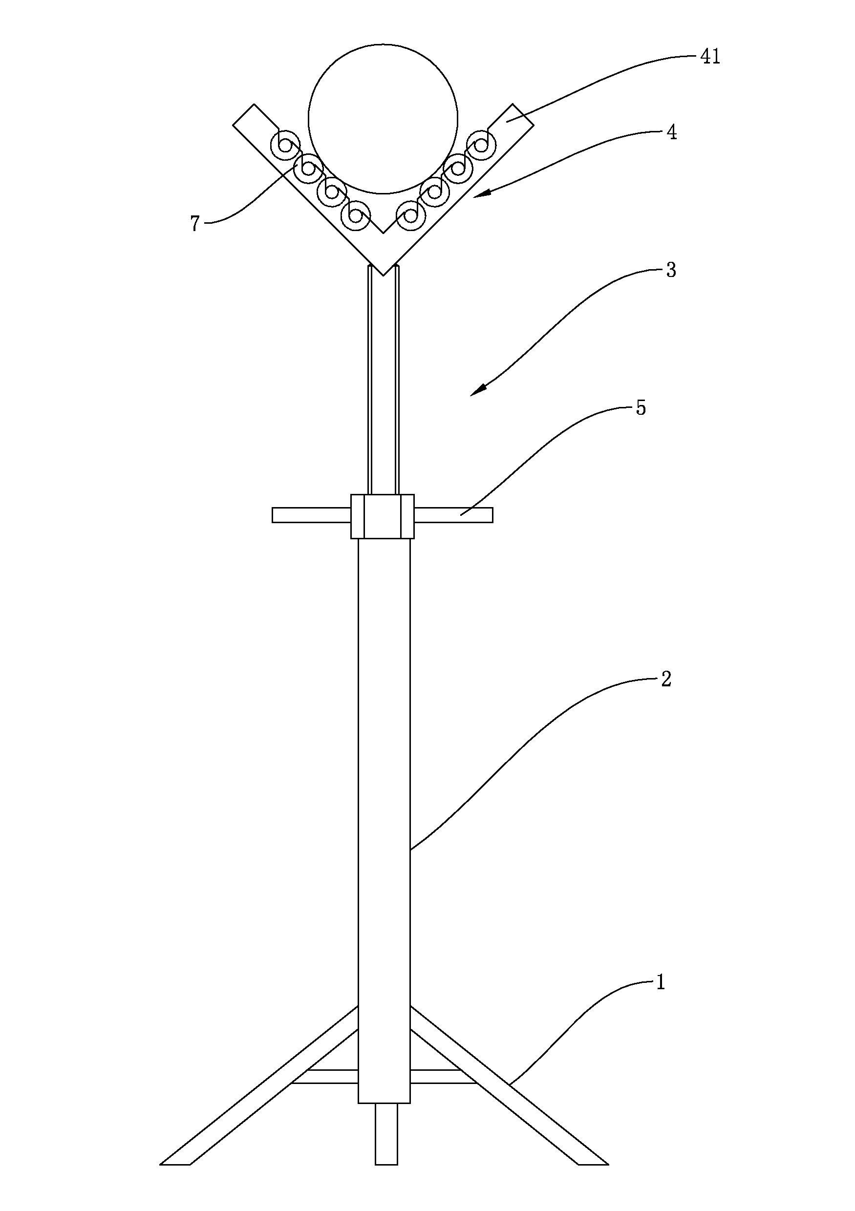
[0034] Such as image 3 As shown, a welding lifting frame includes a bracket 1, a sleeve 2 is installed on the upper end of the bracket 1, a lead screw of a lead screw nut mechanism 3 is sleeved in the sleeve 2, and a nut of the lead screw nut mechanism 3 Installed on the sleeve 2, a wrench 5 is installed on the nut of the lead screw nut mechanism 3, a V-shaped support 4 is installed on the upper end of the lead screw of the lead screw nut mechanism 3, and the two supports of the support 4 The support rollers 7 are respectively installed on the plate portion 41 . The support plate portion 41 is provided with at least one set of angularly symmetrical mounting grooves, and in this embodiment, four sets of angularly symmetrical mounting grooves are provided, and the supporting roller 7 of the supporting roller 7 is axially inserted into the mounting grooves. The installation method of the support roller 7 is detachable installation.

[0035] In the process of welding the workpi...


PUM


Abstract

The invention discloses a welding lift frame, which comprises a bracket, wherein the upper end of the bracket is provided with a sleeve; a lead screw of a lead screw and nut mechanism is sleeved in the sleeve; the upper end of a lead screw of the lead screw and nut mechanism is provided with a supporting member; a nut of the lead screw and nut mechanism is arranged on the sleeve; and the lead screw and nut mechanism can be used for adjusting the height of the supporting member, so that the height of a workpiece can be adjusted at any time to facilitate the welding of the workpiece.

Description

technical field [0001] The invention relates to a lifting frame, in particular to a welding lifting frame for supporting workpiece welding operations. Background technique [0002] At present, during the welding process of workpieces (mainly steel pipes), the steel pipes are placed on a support frame with a fixed height. Because the steel pipes are heavy, it is very inconvenient for workers to operate during welding. They can neither adjust the height of the support frame according to their own needs, nor The steel pipe cannot be turned at any time according to the needs of the welding operation. In addition, the material of the welding support frame currently used is mostly carbon steel, and the direct contact between the carbon steel material and the workpiece is likely to cause corrosion of the raw material, which affects the service life of the raw material and product quality. Contents of the invention [0003] The technical problem to be solved by the present inven...

Claims


Application Information

Patent Timeline
Patent Type & Authority Applications(China)
IPC IPC(8): B23K37/04
Inventor 何军刘勇
Owner 江苏利柏特股份有限公司
Why Eureka
Try Eureka