
Automatic rectifying device in strip steel rolling device

An automatic deviation correction device and automatic deviation correction technology are applied in the field of metallurgical steel rolling machinery, which can solve the problems of the unit no longer being able to produce normally, the surface warping of the strip steel, and damaged equipment, etc., and achieve the effects of small space occupation, energy saving, and convenient maintenance

Inactive Publication Date: 2012-06-20
WISDRI ENG & RES INC LTD
View PDF8 Cites 4 Cited by
  • Summary
  • Abstract
  • Description
  • Claims
  • Application Information

AI Technical Summary

Problems solved by technology

[0002] At present, in the strip steel production and processing line in the metallurgical industry, due to the needs of the process, the strip steel needs to pass through a long-distance hanger roller table without deviation correction rollers, and deviation phenomenon will occur during the operation of the strip steel, resulting in strip Warping occurs on the steel surface, and in severe cases, the strip steel will be broken, causing damage to the equipment, and even causing the unit to no longer be able to produce normally. Therefore, the applicant designed the continuous annealing, galvanizing and color coating in the rolling strip equipment. An automatic deviation correction device is installed on the roller table to ensure the smooth operation of the strip steel equipment

Method used


Image

  • Automatic rectifying device in strip steel rolling device
  • Automatic rectifying device in strip steel rolling device
  • Automatic rectifying device in strip steel rolling device

Examples


Embodiment Construction

[0017] The specific embodiments of the present invention will be further described in detail below in conjunction with the accompanying drawings.

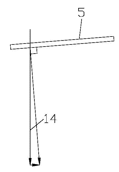
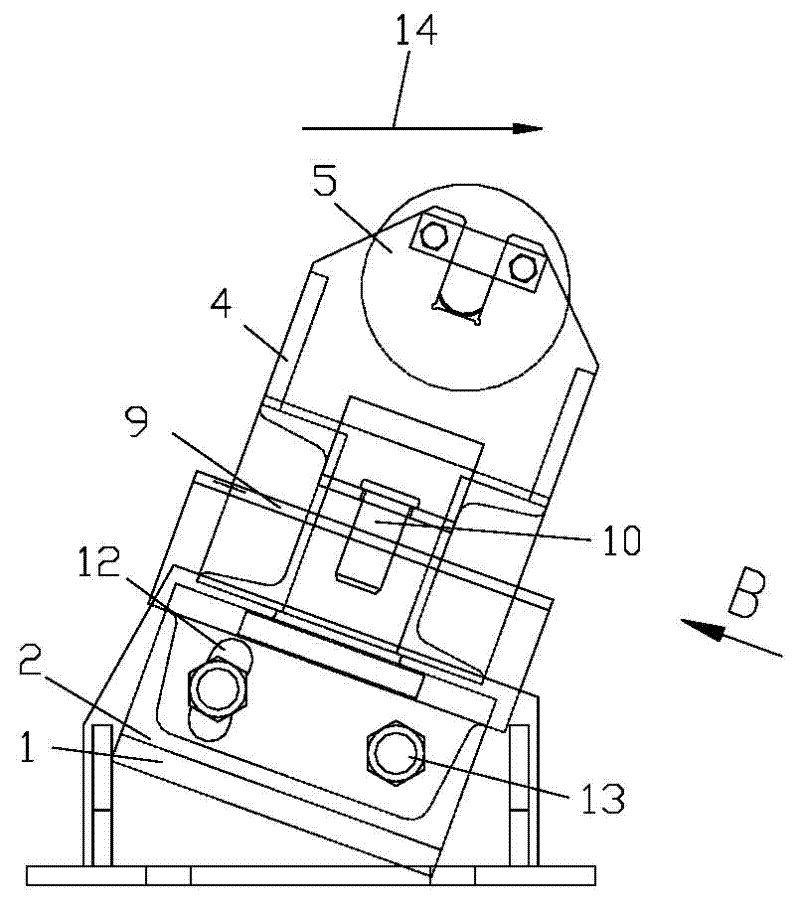
[0018] As shown in the figure, the automatic deviation correction device in the strip rolling equipment involved in the present invention includes a support 1 and a connecting beam 2, and the support 1 and the connecting beam 2 are fixed by fastening screws 13, including The fixed shaft 3, the roller bracket 4 and the automatic deviation correction roller 5, the lower part of the fixed shaft 3 is fixed on the middle position of the two bearings 1 on the connecting beam 2, and the two ends of the automatic deviation correction roller 5 are respectively arranged on the roller support 4, the middle of the bottom of the roller bracket 4 is hinged with the upper end of the fixed shaft 3.

[0019] A circular hole 6 is provided at the middle position of the two supports 1 on the connecting beam 2 , and the lower part of the fixed shaft 3 ...


PUM


Abstract

The invention relates to an automatic rectifying device in a strip steel rolling device, which comprises support bases and a connection beam, wherein the support bases and the connection beam are fixed through screws. The automatic rectifying device comprises a fixing shaft, a roller support and an automatic rectifying roller. The lower portion of the fixing shaft is fixed at a middle position between two support bases on the connection beam, two ends of the automatic rectifying roller are respectively arranged at two ends of the roller support, and the middle of the bottom of the roller support is hinged with the upper end of the fixing shaft. Through the technical scheme, when strip steel is deviated, the gravity line of the of the strip steel deviates from the central line of the automatic rectifying roller, the automatic rectifying roller is deflected under compression of gravity, and the automatic rectifying roller just generates centripetal rectifying force along the deflecting direction. The automatic rectifying device requires no power driving, saves energy, and is simple in method, small in occupied space, simple in installation, convenient to overhaul and capable of being installed on a hanging frame track, and the existing rectifying devices have no installation space on the hanging frame track due to requirements for space structure and technology process distribution.

Description

technical field [0001] The invention relates to a metallurgical steel rolling machine, in particular to an automatic deviation correction device in rolling strip steel equipment. Background technique [0002] At present, in the strip steel production and processing line in the metallurgical industry, due to the needs of the process, the strip steel needs to pass through a long-distance hanger roller table without deviation correction rollers, and deviation phenomenon will occur during the operation of the strip steel, resulting in strip Warping occurs on the steel surface, and in severe cases, the strip steel will be broken, and the equipment will be damaged, and even the unit can no longer be produced normally. Therefore, the applicant designed the continuous annealing, galvanizing and color coating in the rolling strip equipment. An automatic deviation correction device is installed on the roller table to ensure the smooth operation of the strip steel equipment. Contents...

Claims


Application Information

Patent Timeline
IPC IPC(8): B65H23/038
Inventor 郑祥臣徐启发
Owner WISDRI ENG & RES INC LTD
Learn More